
Structure for preventing submersion of device

a technology for preventing device submersion and structure, which is applied in the direction of positive displacement liquid engine, human health protection, liquid fuel engine, etc., can solve the problems of high probability of explosion or the like, high cost of oil-submerged pump (water-submerged pump), and the malfunction or failure of the device can be prevented, prevent the occurrence of explosion, and prevent the effect of submersion of the devi

Active Publication Date: 2018-02-27
SHOWA KIKI KOGYO CO LTD
View PDF11 Cites 0 Cited by
  • Summary
  • Abstract
  • Description
  • Claims
  • Application Information

AI Technical Summary

Benefits of technology

[0019](1) The enclosure is provided with an opening, and thereby the internal chamber of the enclosure always communicates with an external air, so that it becomes possible to release heat generated from the device and oil vapor. Thus, it becomes possible to prevent the occurrence of malfunction or failure of the device due to the heat. It also becomes possible to prevent the occurrence of explosion due to the oil vapor, thereby providing an extremely-safe state.
[0020](2) The opening is provided only in the bottom portion of the enclosure, or only in the lateral portion of the enclosure at a position below the installation position of the device. Thus, even in a situation where the enclosure is submerged in water, a confined air space is formed in the internal chamber of the enclosure. Thus, submersion of the device can be prevented by installing the device in an area where the confined air space is to be formed. Therefore, even in the event of tsunami or flooding, it becomes possible to avoid a situation where the device becomes unusable, so that the operation of the device can be continued. This makes it possible to prevent damage from spreading to thereby allow rapid disaster recovery.
[0021](3) Measures against a disaster such as tsunami or flooding can be taken by a commonly-used inexpensive device, and work such as maintenance in the event of a malfunction or failure of the pump can be performed with good efficiency, so that it becomes possible toe a device submersion preventing structure having excellent economic efficiency and convenience.

Problems solved by technology

Thus, during use in a normal state, heat generated from the pump stays within the watertight enclosure, so the heat is likely to cause a malfunction or failure of the pump, particularly, when the pump is continuously used for a long period of time.
Moreover, in the case where the pump is an oil feed pump, oil vapor stays within the watertight enclosure, and thus leads to a situation where explosion or the like is extremely highly likely to occur.
On the other hand, in the case of using an oil-submersible pump (water-submersible pump), the oil-submersible pump (water-submersible pump) is much more expensive than a commonly-used pump, and is required to take a considerable amount of cost, time and effort, specifically, required to be extracted from an inside of the underground tank during maintenance in the event of a malfunction or failure of the pump.

Method used


Image

  • Structure for preventing submersion of device
  • Structure for preventing submersion of device
  • Structure for preventing submersion of device

Examples


first embodiment

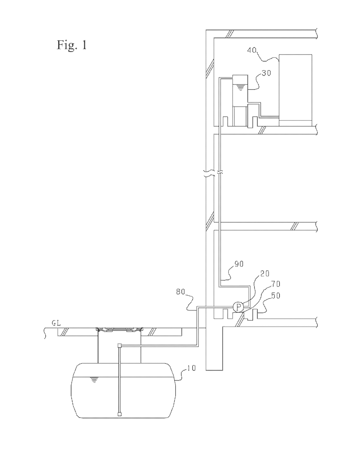
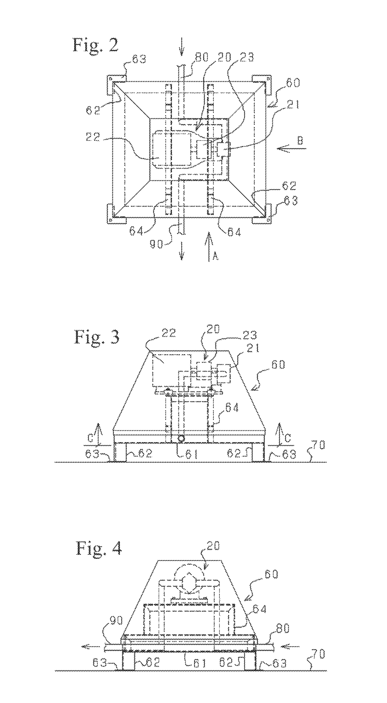
[0047]FIG. 2 is a top plan view illustrating a device submersion preventing structure according a first embodiment of the present invention, wherein the device submersion preventing structure is applied to a pump in FIG. 1, and FIG. 3, FIG. 4 and FIG. 5 are, respectively, a view of the device submersion preventing structure when viewed in a direction indicated by the arrowed line A in FIG. 2, a view of the device submersion preventing structure when viewed in a direction indicated by the arrowed line B in FIG. 2, and a sectional view taken along the line C-C in FIG. 3.

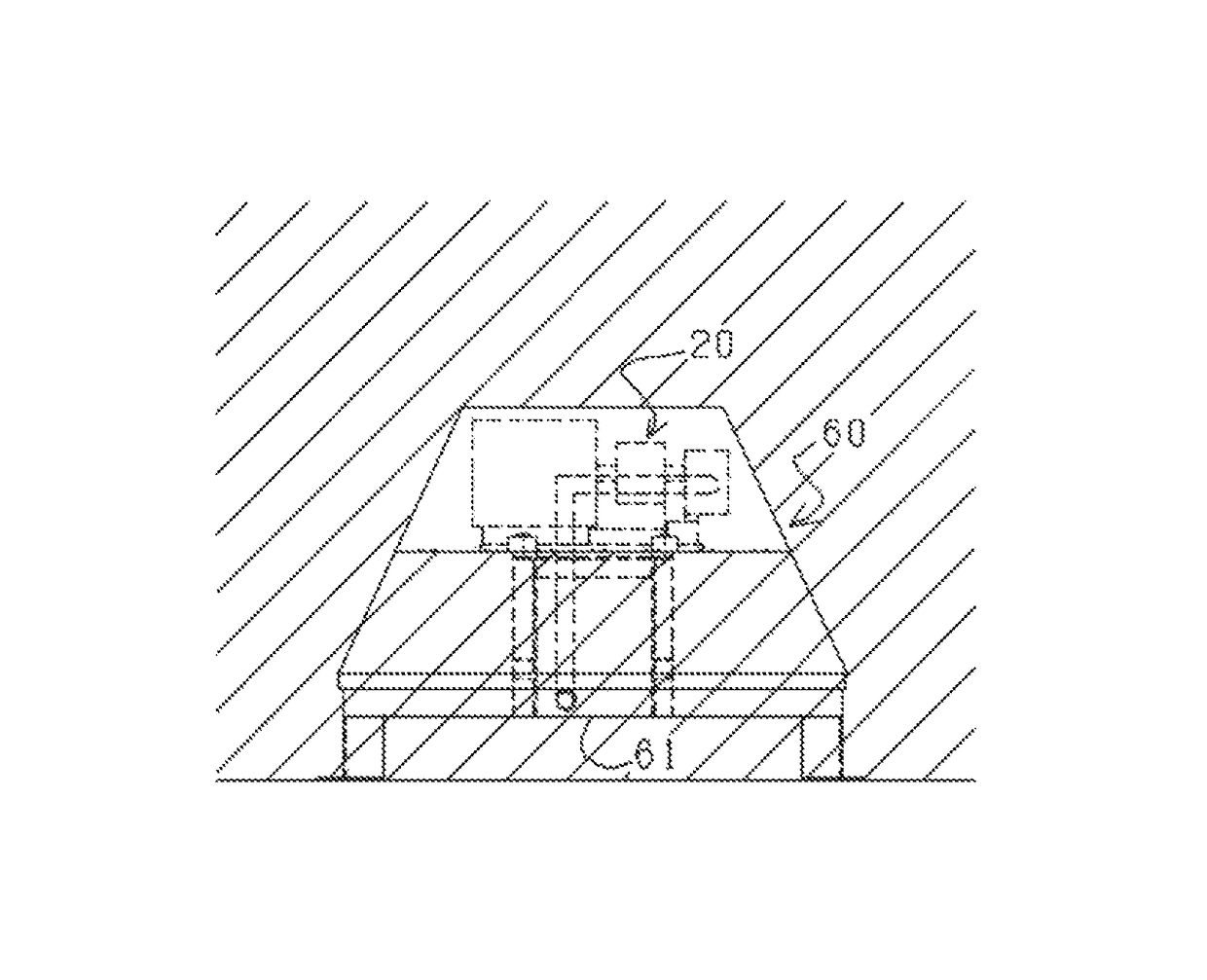
[0048]The pump 20 is installed in an enclosure 60. The enclosure 60 is formed in a four-sided truncated pyramid shape, and configured such that an opening 61 is provided only in a bottom portion thereof, and a remaining portion thereof is formed as an air-confining structure. This enclosure 60 is disposed above a base 70 provided inside the oil barrier dam 50 (see FIG. 1). More specifically, four legs 62 each formed of...

second embodiment

[0056]FIG. 9 is a top plan view illustrating a device submersion preventing structure according a second embodiment of the present invention, wherein the device submersion preventing structure is applied to the pump in the system illustrated in FIG. 1. FIG. 10 is a view of the device submersion preventing structure when viewed in a direction indicated by the arrowed line D in FIG. 9, and FIG. 11 is a sectional view taken along the line E-E in FIG. 10. In FIGS. 9 to 11, the same element or component as that in the first embodiment is assigned with the same reference sign, and its description will be omitted.

[0057]In the second embodiment, a float member 100 floatable on water is disposed beneath an opening 61 of a bottom portion of an enclosure 60 movably in an up-down direction, to serve as a blocking member configured to open and close the opening 61. The float member 100 integrally has a flange 101 provided in a peripheral edge region thereof, and a float body 102 surrounded by th...

third embodiment

[0059]FIG. 13 is a top plan view illustrating a device submersion preventing structure according a third embodiment of the present invention, wherein the device submersion preventing structure is applied to the pump in the system illustrated in FIG. 1. FIG. 14 is a view of the device submersion preventing structure when viewed in a direction indicated by the arrowed line F in FIG. 13. In FIGS. 13 to 14, the same element or component as that in the first and second embodiments is assigned with the same reference sign, and its description will be omitted.

[0060]In the third embodiment, a blocking member 110 is disposed beneath an opening of a bottom portion of an enclosure 60 to open and close the opening 61, wherein the blocking member 110 is configured to be moved in an up-down direction by a drive mechanism.

[0061]The blocking member 110 integrally has a flange 111 provided in a peripheral edge region thereof, and a blocking body 112 surrounded by the flange 111 and formed in a four-...


PUM


Abstract

Provided is a device submersion preventing structure which is capable of releasing heat generated from a device such as a pump and oil vapor, and preventing submersion of the device. The device submersion preventing structure comprises an enclosure having an internal chamber 60 for installing a pump 20 therein, wherein the enclosure 60 is configured such that an opening 61 is provided only in a bottom portion thereof, and a remaining portion thereof is formed as an air-confining structure.

Description

TECHNICAL FIELD[0001]The present invention relates to a device submersion preventing structure, specifically, a structure for, in the event of tsunami, floods or the like, preventing a device such as a pump from being submerged in water.BACKGROUND ART[0002]For example, as for a pump for feeding oil stored in an underground tank to a private power generator, it is often installed on a ground surface (GL) close to the underground tank, in relation to a suction head of the pump, and generally no measure against submersion was taken. However, after the Great East Japan Earthquake, measures for preventing submersion of a pump have become considered to be important, and various pump submersion prevention measures are currently being studied and taken.[0003]Heretofore, as a pump submersion prevention measure, there has been known a structure configured to install a pump in a watertight box or enclosure (watertight structural member), as disclosed in the following Patent Document 1. There h...

Claims


Application Information

Patent Timeline
Patent Type & Authority Patents(United States)
IPC IPC(8): F04B53/00E04H9/14F04D29/60F04B23/02
CPCF04B53/00E04H9/145F04D29/606F04B23/021F04D29/601F04B23/02Y02A10/30Y02A50/00
Inventor MAESHIBA, SHINSUKE
Owner SHOWA KIKI KOGYO CO LTD
Learn More