Photo-optic comparative geolocation system

a geolocation system and photooptic technology, applied in the field of photo -, can solve the problems of inability to use geolocation devices or methods, communication networks may be unavailable,

Active Publication Date: 2018-01-30
LUCAS FISHER VANCE
View PDF1 Cites 0 Cited by
  • Summary
  • Abstract
  • Description
  • Claims
  • Application Information

AI Technical Summary

Problems solved by technology

For example, communication networks may be unavailable in some remote areas, making some geolocation devices or methods impossible.

Method used


Image

  • Photo-optic comparative geolocation system
  • Photo-optic comparative geolocation system
  • Photo-optic comparative geolocation system

Examples


Embodiment Construction

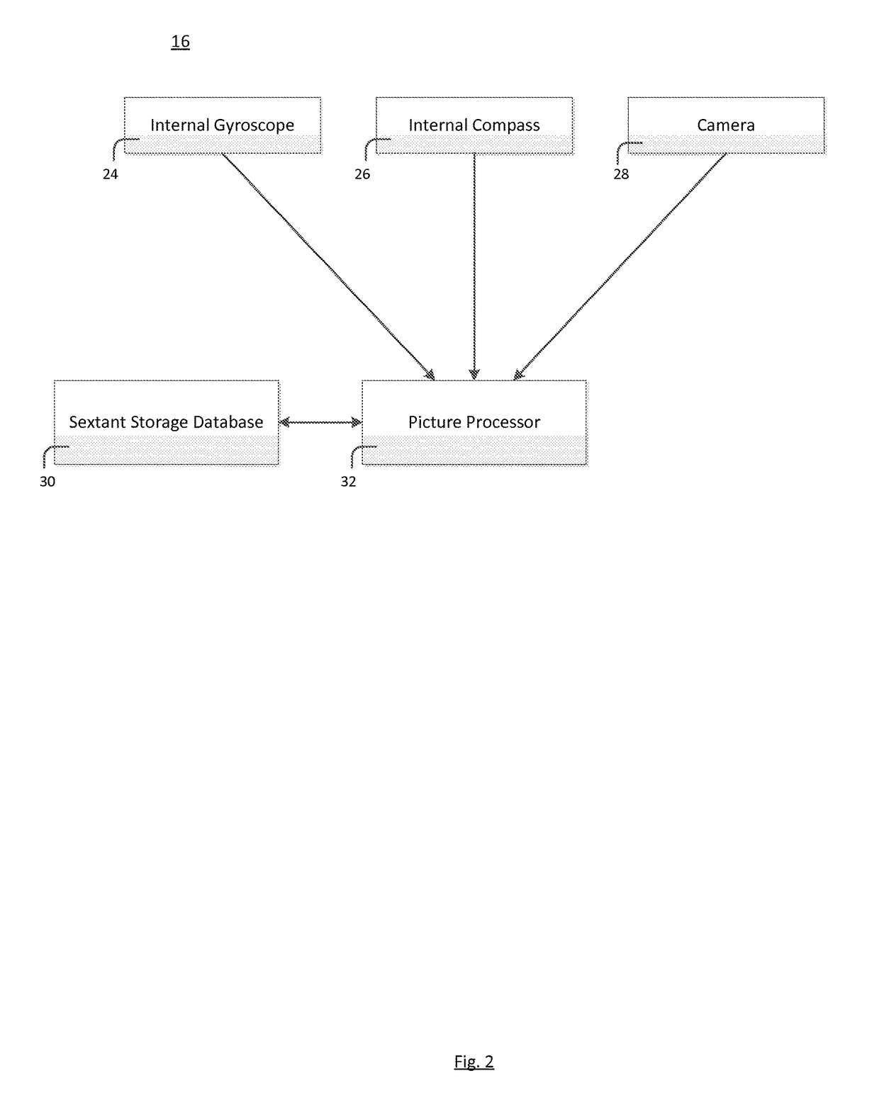
[0014]A photo-optic comparative geolocation system has been developed. It should be understood that the present invention may be utilized in a broad range of commercial industries, including but not limited to transportation, telecommunications, and security. Additionally, the present invention may be used for personal or military purposes. The present invention provides the capability to calculate the geolocation of an object—without the need for any type of signal transmission over a network—by comparing digital map data with visually observable, optically captured reference points. Additionally, the present invention provides the capability to store various images relating to an object's geolocation, including surrounding landscape or architectural images. Features of the system include: the ability to capture surrounding image data; the ability to store image data within the system; an interface between initial image data and stored geolocation data; an internal digital sextant;...


PUM


Abstract

A photo-optic comparative geolocation system for calculating the location of an object has been developed. The apparatus includes optic sensors that capture surrounding location data, an interface that maps the optic sensor data, a storage database containing prior optical and location data, a digital sextant that provides data calculated using magnetic or celestial references, a data processor that compares the mapped data to stored data and calculates current location based on the comparison analysis, and a visual display for location information.

Description

CROSS-REFERENCE TO RELATED APPLICATIONS[0001]This application claims the benefit of, and priority to, U.S. Provisional Application No. 62 / 022,934 entitled “Photo-Optic Comparative Geolocation System” that was filed on Jul. 10, 2014.BACKGROUND OF INVENTION[0002]Many industries, both commercial and military in nature, utilize geolocation (i.e., location on the surface of the earth) systems for navigation, communications, and other purposes. In addition, personal use of geolocation systems has become prevalent in recent years. Typically, global positioning systems (“GPS”) or other types of satellite or communications networks are used in order to calculate an exact location of the user.[0003]Certain capabilities currently exist, but these methods of geolocation involve the transmission of signals, whether via satellite or other type of communications network. In some instances, a user may need to calculate his geolocation without the transmission of signals. For example, communication ...

Claims


Application Information

Patent Timeline
Patent Type & Authority Patents(United States)
IPC IPC(8): H04N7/18G06F17/30G01S5/16G06T7/73G06K9/00
CPCG06F17/3028G01S5/16G06T7/74G06K9/00671G06T2207/30252G06T2207/30244G06V20/20G06F16/51
Inventor LUCAS, FISHER VANCE
Owner LUCAS FISHER VANCE
Why Eureka
Try Eureka