
Method for estimating cable length in Ethernet system and receiver thereof

a technology of ethernet system and cable length, applied in the field of channel estimation technology, can solve the problems of inability to maintain the same effect in various environments, inability to have the following three elements at the same time, and inability to have stability, simple calculation and high accuracy, so as to achieve the effect of easy obtaining cable length information

Active Publication Date: 2018-01-30
REALTEK SEMICON CORP
View PDF24 Cites 0 Cited by
  • Summary
  • Abstract
  • Description
  • Claims
  • Application Information

AI Technical Summary

Benefits of technology

The present invention provides a method and device for estimating the length of cable in an Ethernet system accurately and easily. This is done by using information from a feedback equalizer and a feed-forward equalizer of the receiver when connected. This approach ensures that the cable length is taken into account when estimating the channel response and sampling phase difference. Ultimately, this technology allows for precise and straightforward tracking of the cable's length.

Problems solved by technology

Although many manners at present can be used to provide cable length information of an ultra-high-speed Ethernet system, these manners fail to have the following three elements at the same time, i.e., stability, simple calculation and high accuracy.
For example, the manner of estimating a cable length by measuring energy of a received signal is easily affected by different power of a transmitting end, and thus cannot maintain the same effect in various environments and cannot provide good stability.
It is found according to a simulation result that the accuracy thereof is quite high, but the problem lies in that the actual hardware implementation requires too high cost.
As calculation of DFT (Discrete Fourier Transform) of many points is required for accurate calculation of components of 6 MHz and 43 MHz, this involves a large number of multiplications and additions, so that the IC area becomes large and the cost increases, which is difficult to meet the actual demand.

Method used


Image

  • Method for estimating cable length in Ethernet system and receiver thereof
  • Method for estimating cable length in Ethernet system and receiver thereof
  • Method for estimating cable length in Ethernet system and receiver thereof

Examples


Embodiment Construction

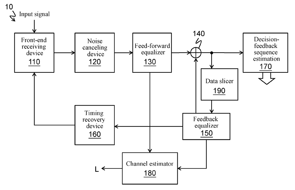
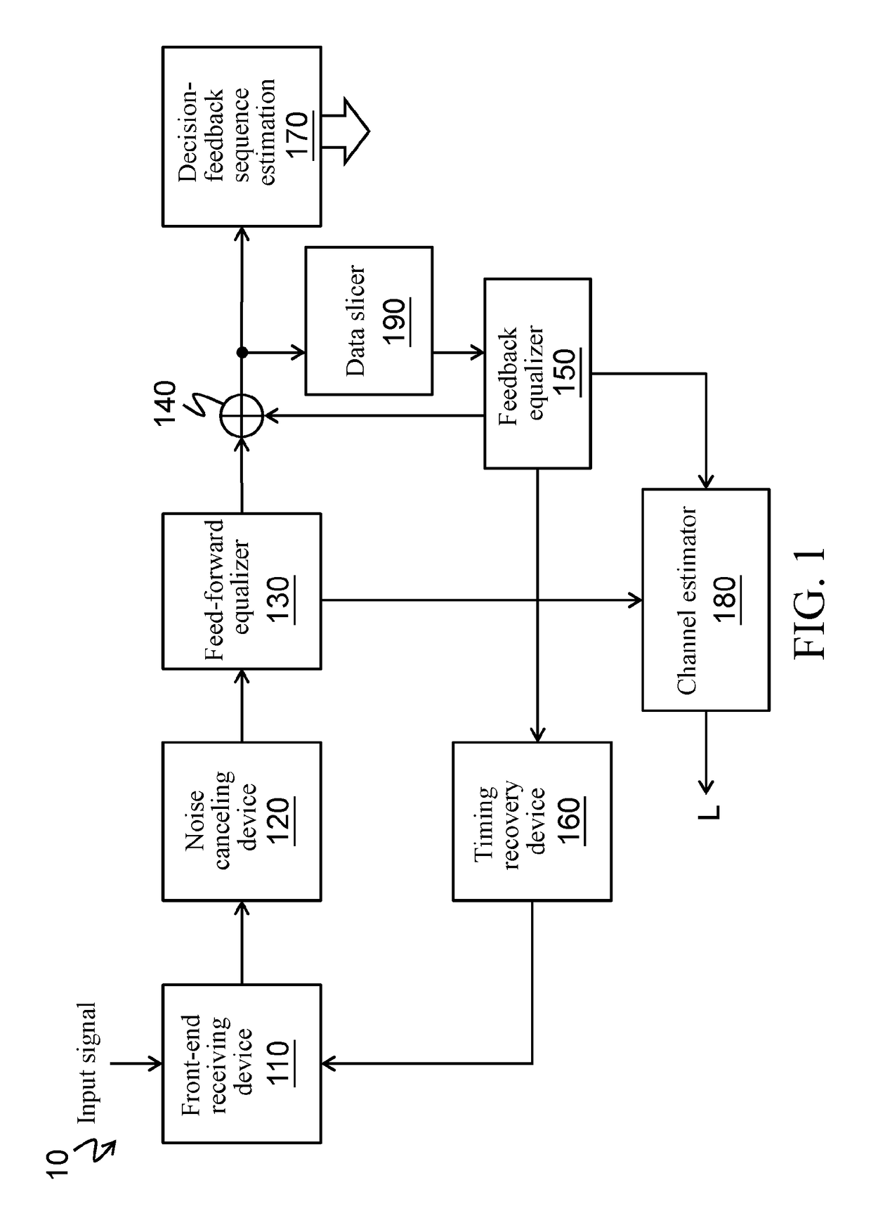
[0017]Referring to FIG. 1, an Ethernet system receiver 10 includes a front-end receiving device 110, a noise canceling device 120, a feed-forward equalizer (FFE) 130, an adder 140, a feedback equalizer (FBE) 150, a timing recovery device 160, a decision-feedback sequence estimation (DFSE) 170, a channel estimator 180 and a data slicer 190.

[0018]The front-end receiving device 110, the noise canceling device 120, the FFE 130, the adder 140, and the DFSE 170 are electrically connected in sequence. The FBE 150 is electrically connected to the adder 140, and the timing recovery device 160 is electrically connected between the front-end receiving device 110 and the FBE 150. The channel estimator 180 is electrically connected to the FFE 130 and the FBE 150. Herein, two input ends of the adder 140 respectively are electrically connected to the FFE 130 and the FBE 150, and an output end of the adder 140 is electrically connected to the DFSE 170. The data slicer 190 is electrically connected ...


PUM


Abstract

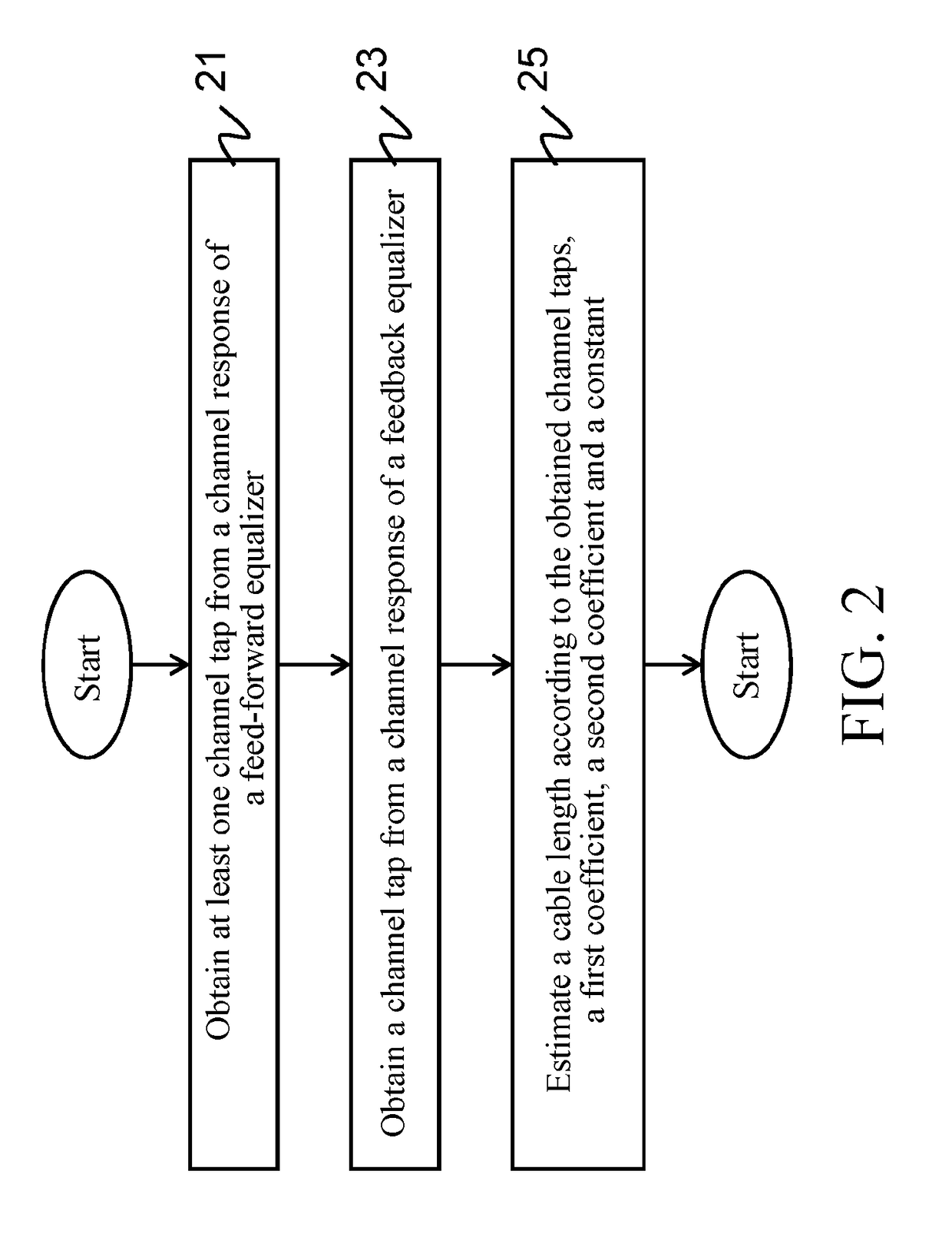
A method for estimating cable length in an Ethernet system and a receiver thereof are applicable to an Ethernet system. The method for estimating cable length includes obtaining a channel tap from channel information of a feedback equalizer in the Ethernet system and estimating a cable length according to the channel tap, a first coefficient and a constant.

Description

CROSS-REFERENCES TO RELATED APPLICATIONS[0001]This non-provisional application claims priority under 35 U.S.C. §119(a) on Patent Application No. 102129205 filed in Taiwan, R.O.C. on 2013 Aug. 14, the entire contents of which are hereby incorporated by reference.BACKGROUND[0002]Technical Field[0003]The present invention relates to a channel estimation technology, and more particularly, to a method for estimating cable length in an Ethernet system and a receiver thereof.[0004]Related Art[0005]In an Ethernet system, use of channels can be better detected and controlled if cable length information and cable status are provided. Therefore, a lot of manners for estimating a cable length have been proposed, for example, estimating a cable length by measuring energy of a received signal, or estimating a cable length by observing a relation between spectrum of a received signal and the cable length. Although many manners at present can be used to provide cable length information of an ultra-...

Claims


Application Information

Patent Timeline
Patent Type & Authority Patents(United States)
IPC IPC(8): H04L12/26G01B7/02G06F11/22
CPCG06F11/22G01B7/026
Inventor WANG, SHIH-WEIHUANG, LIANG-WEISU, CHING-YAOCHUANG, SHENG-FU
Owner REALTEK SEMICON CORP
Learn More