Bone screw, and bone fixation system and method

a bone screw and screw body technology, applied in the field of bone screw and bone fixation system and method, can solve the problems of poor trabecular bone quality, limited screw length selection to the detriment of stable fixation, and insufficient ilium for its own fixation area,

Active Publication Date: 2018-01-09
SPINOLOGICS
View PDF59 Cites 2 Cited by
  • Summary
  • Abstract
  • Description
  • Claims
  • Application Information

AI Technical Summary

Benefits of technology

[0006]The embodiments of the present invention reduce the difficulties and disadvantages of the aforesaid designs and treatments.
[0007]Broadly, from one aspect of the present invention, there is provided a bone screw which can engage with bone and which is arranged to be interconnectable with a fastening means in order to limit movement of the bone screw away from the engaged bone in use. One application of the bone screw is in the spinal-pelvic region, such as for joining together the iliac and sacrum bones. The threaded bone screw together with the interconnecting fastening means helps to prevent screw pull out from the engaged bone. The bone screw can also be connected to bones or implants in the spine by connectors.

Problems solved by technology

However, the sacrum has a thin cortical shell often with poor trabecular bone quality which limits screw length selection to the detriment of stable fixation.
The ilium offers adequate fixation area but is not sufficient on its own as it may encounter problems of screw pullout and loosening over time.
Moreover, current techniques of attempting to limit the extent of screw pullout have limited success and are surgically complex which can undesirably increase operating times.

Method used


Image

  • Bone screw, and bone fixation system and method
  • Bone screw, and bone fixation system and method
  • Bone screw, and bone fixation system and method

Examples


Embodiment Construction

[0062]This invention is not limited in its application to the details of construction and the arrangement of components set forth in the following description or illustrated in the drawings. The invention is capable of other embodiments and of being practiced or of being carried out in various ways. Also, the phraseology and terminology used herein is for the purpose of description and should not be regarded as limiting. The use of “including”, “comprising”, or “having”, “containing”, “involving” and variations thereof herein, is meant to encompass the items listed thereafter as well as, optionally, additional items. In the following description, the same numerical references refer to similar elements.

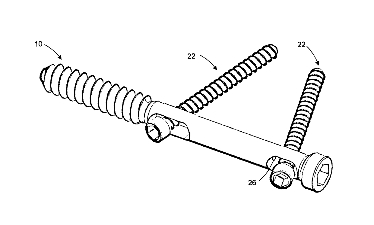
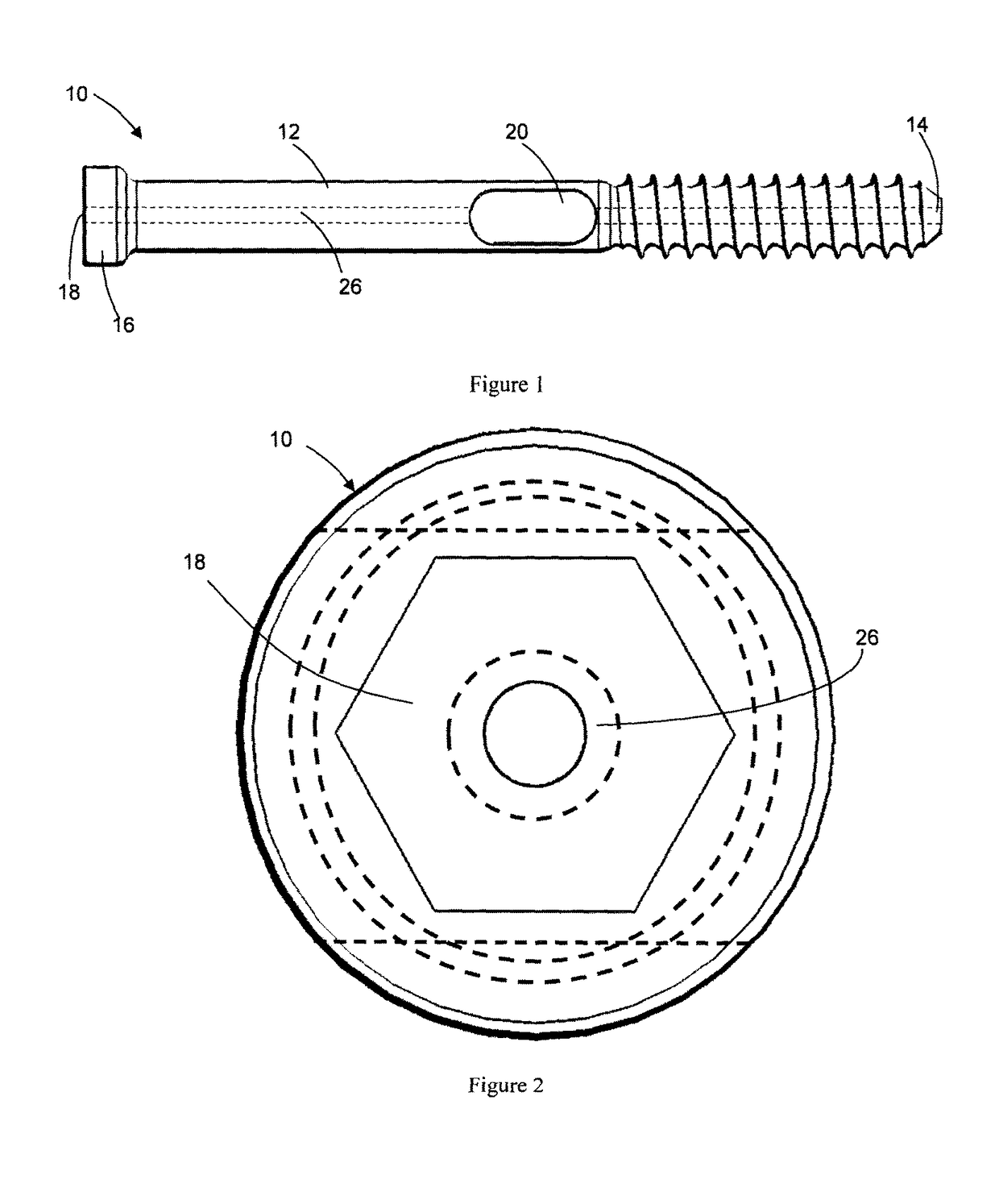
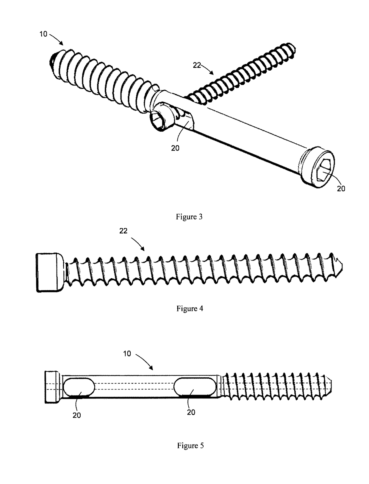
[0063]Broadly, embodiments of the invention relate to a bone screw which can engage with bone and which is arranged to be interconnectable with a fastening means in order to limit movement of the bone screw away from the engaged bone in use. One application of an embodiment of the pres...


PUM


Abstract

A bone screw for pelvic bone fixation, the bone screw comprising an elongate body having a first end which is threaded for engaging at least one bone in the pelvic region, a second end comprising a screw head, and at least one opening across the length of the elongate body for adjustably receiving a fastening means to limit movement of the bone screw away from the engaged bone in use, wherein the at least one opening is shaped such that the position of the fastening means relative to the elongate body of the bone screw can be adjusted. A system for bone fixation in the pelvic region includes the bone screw and the fastening means.

Description

CROSS-REFERENCE TO RELATED APPLICATIONS[0001]The present application is a U.S. national stage application claiming the benefit of International Application No. PCT / CA2012 / 000625, filed on Jun. 28, 2012, which claims priority from U.S. Provisional Patent Application No. 61 / 502,203, filed Jun. 28, 2011, the entire contents of which are incorporated herein by reference in their entirety.FIELD OF THE INVENTION[0002]The present invention relates to a bone screw, and bone fixation system and method, and more specifically although not exclusively to a bone screw, and bone fixation system and method for the spinal-pelvic region.BACKGROUND OF THE INVENTION[0003]Spinal-pelvic deformities, trauma, fractures, tumors, inflammation and degeneration can necessitate surgical intervention to secure bones to each other or implants to the bone. Implants such as rods and plates can be used to replace or augment bone. Fixation devices such as hooks, wires, screws and connectors can be used to secure the...

Claims


Application Information

Patent Timeline
Patent Type & Authority Patents(United States)
IPC IPC(8): A61B17/04A61B17/70A61B17/88A61B17/68A61F2/08A61B17/86
CPCA61B17/8625A61B17/68A61B17/7055A61B17/8645A61B17/88A61B17/8872A61B17/864A61B2017/8655H05K999/99
Inventor PARENT, STEFANMAC-THIONG, JEAN-MARCLABELLE, HUBERTDRISCOLL, MARK
Owner SPINOLOGICS
Why Eureka
Try Eureka