
Dressing apparatus, polishing apparatus having the dressing apparatus, and polishing method

a technology of dressing apparatus and polishing apparatus, which is applied in the direction of metal-working apparatus, manufacturing tools, abrasive surface conditioning devices, etc., can solve problems such as the reduction of the polishing ra

Active Publication Date: 2018-01-02
EBARA CORP
View PDF25 Cites 0 Cited by
  • Summary
  • Abstract
  • Description
  • Claims
  • Application Information

AI Technical Summary

Benefits of technology

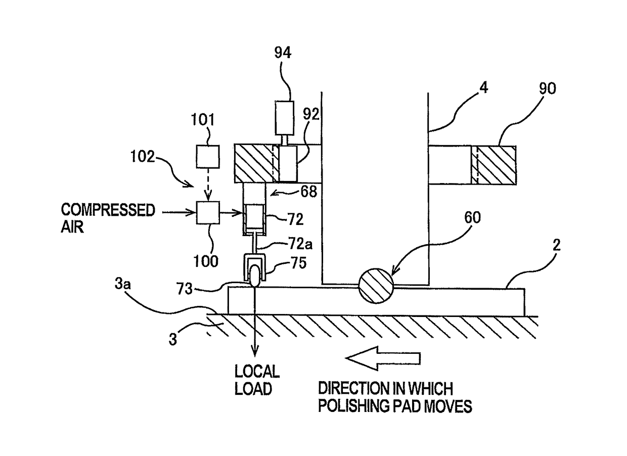
[0007]It is an object to provide a dressing apparatus capable of keeping an entire dressing surface of a dresser in uniform sliding contact with a polishing surface of a polishing pad, and capable of uniformly dressing the polishing surface of the polishing pad in its entirety. It is also an object to provide a polishing apparatus having such a dressing apparatus.

Problems solved by technology

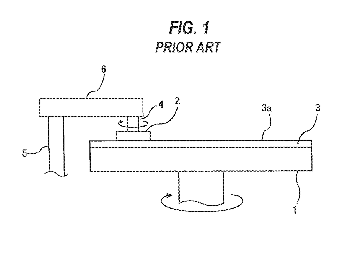
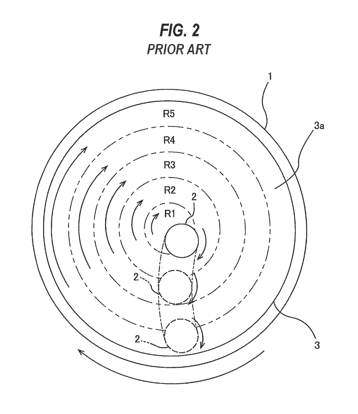
As the substrate is continuously polished with use of the polishing pad, minute irregularities that constitute the surface of the polishing pad are flattened, thus causing a decrease in a polishing rate.

Method used


Image

  • Dressing apparatus, polishing apparatus having the dressing apparatus, and polishing method
  • Dressing apparatus, polishing apparatus having the dressing apparatus, and polishing method
  • Dressing apparatus, polishing apparatus having the dressing apparatus, and polishing method

Examples


Embodiment Construction

[0038]Embodiments will be described below with reference to the drawings. In FIGS. 3 through 17, identical or corresponding components will be denoted by identical reference numerals, and repetitive descriptions thereof are omitted.

[0039]FIG. 3 is a schematic view of a polishing apparatus 10. As shown in FIG. 3, the polishing apparatus 10 has a polishing table 1 supporting a polishing pad 3 that serves as a polishing tool, a polishing head 12 for holding a substrate W, such as a wafer, and pressing the substrate W against the polishing pad 3 on the polishing table 1, and a dressing apparatus (a dressing unit) 14 for dressing a polishing surface 3a of the polishing pad 3. The polishing pad 3 is attached to the upper surface of the polishing table 1, and has an upper surface serving as the polishing surface 3a for polishing the substrate W. Instead of the polishing pad 3, fixed abrasive grains or a polishing cloth may be used as the polishing tool.

[0040]The polishing table 1 is couple...


PUM


Abstract

A dressing apparatus capable of bringing an overall dressing surface of a dresser into uniform sliding contact with a polishing surface of a polishing pad and capable of uniformly dressing the overall polishing surface of the polishing pad is disclosed. The dressing apparatus includes a dresser configured to rub against a polishing surface to dress the polishing surface that is used for polishing a substrate, a dresser shaft that applies a load to the dresser, at least one load-applying device configured to apply a downward load to a part of a peripheral portion of the dresser, and an operation controller configured to control operation of the load-applying device.

Description

CROSS REFERENCE TO RELATED APPLICATION[0001]This document claims priority to Japanese Patent Application Number 2013-102970 filed May 15, 2013, the entire contents of which are hereby incorporated by reference.BACKGROUND[0002]Chemical mechanical polishing (CMP) apparatus is widely known as a polishing apparatus for polishing a surface of a substrate, such as a wafer. This polishing apparatus polishes the substrate by holding the substrate with a top ring and pressing the substrate against a polishing pad on a polishing table while moving the polishing table and the top ring relative to each other. During polishing of the substrate, the polishing pad is supplied with a polishing liquid (or slurry) from a polishing liquid supply nozzle, so that the surface of the substrate is polished by a chemical action of the polishing liquid and a mechanical action of abrasive grains that are contained in the polishing liquid.[0003]As the substrate is continuously polished with use of the polishin...

Claims


Application Information

Patent Timeline
Patent Type & Authority Patents(United States)
IPC IPC(8): B24B53/017B24B53/00
CPCB24B53/017B24B53/005
Inventor NAGAI, SATOSHIOGURA, SUGURUHAMAURA, KAORU
Owner EBARA CORP
Learn More