
Magnetic coupling motor drive for surgical cutting instrument

a technology of magnetic coupling and cutting instrument, which is applied in the field of cutting tools, can solve problems such as reducing the life of the unit, and achieve the effects of reducing friction, reducing vibration, and reducing conta

Active Publication Date: 2018-01-02
SMITH & NEPHEW INC
View PDF6 Cites 4 Cited by
  • Summary
  • Abstract
  • Description
  • Claims
  • Application Information

AI Technical Summary

Benefits of technology

The patented motor drive has the advantage of reducing friction and wear and tear on the motor, which may increase its life. This is achieved by using an air gap between the motor and the load it is driving, instead of direct contact.

Problems solved by technology

However, this arrangement can be difficult to clean, and serviceability of the motor drive unit may be impaired, potentially reducing the lifetime of the unit.

Method used


Image

  • Magnetic coupling motor drive for surgical cutting instrument
  • Magnetic coupling motor drive for surgical cutting instrument
  • Magnetic coupling motor drive for surgical cutting instrument

Examples


Embodiment Construction

[0037]The subject innovation is now described with reference to the drawings, wherein like reference numerals are used to refer to like elements throughout. In the following description, for purposes of explanation, numerous specific details are set forth in order to provide a thorough understanding of the present invention. It may be evident, however, that the present invention may be practiced without these specific details. In other instances, well-known structures and devices are shown in block diagram form in order to facilitate describing the present invention.

[0038]As used in this application, the term “or” is intended to mean an inclusive “or” rather than an exclusive “or.” That is, unless specified otherwise, or clear from context, “X employs A or B” is intended to mean any of the natural inclusive permutations. That is, if X employs A, X employs B, or X employs both A and B, then “X employs A or B” is satisfied under any of the foregoing instances. Moreover, articles “a” a...


PUM


Abstract

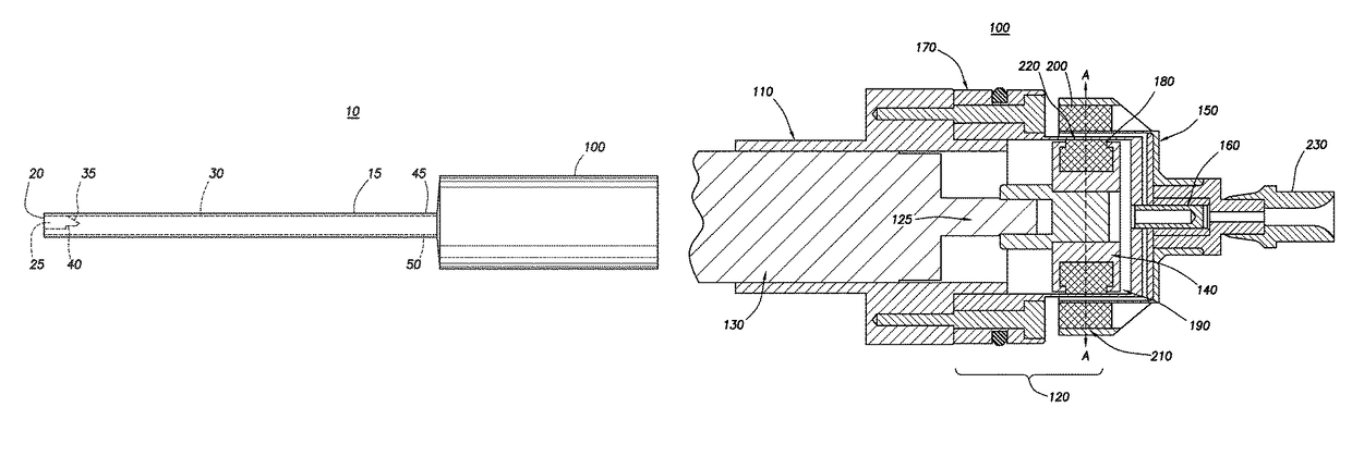
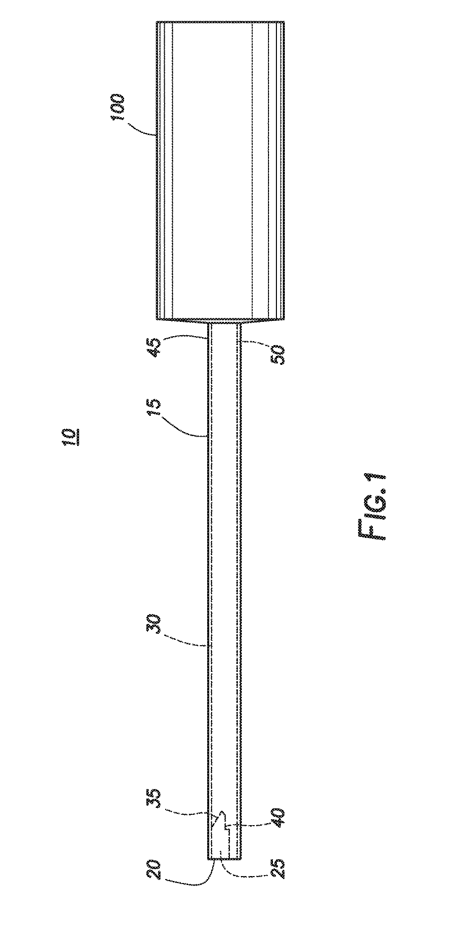
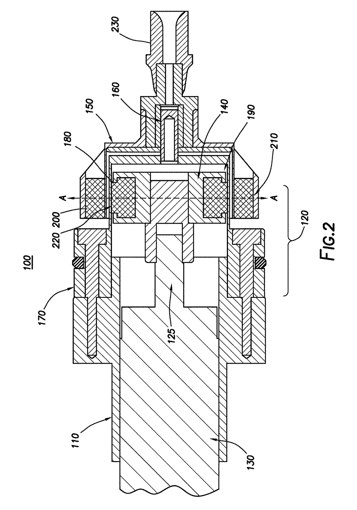
Apparatus and methods for a magnetic coupling motor drive for a surgical cutting instrument. A magnetic coupling motor drive unit includes a motor housing containing a motor and a magnetic drive hub assembly, the magnetic drive hub assembly having a drive hub and a driven hub, the driven hub rotating about a driven hub spindle, the driven hub spindle attached to a seal cap, the seal cap sealing the drive hub and the motor to the motor housing, wherein the drive hub includes an array of magnets aligned to a respective array of magnets in the driven hub.

Description

BACKGROUND OF THE INVENTION[0001]The present invention generally relates to cutting tools, and more particularly to a magnetic coupling motor drive for a surgical cutting instrument.[0002]Arthroscopic instruments can be used to cut tissue mechanically in various parts of a body, such as, for example, a knee, using a blade that is rotated, or otherwise brought into contact with the tissue to be cut. These tools generally include a rotary blade driven by a motor drive. A drive adapter, which connects the motor drive to the blade, is directly attached to the motor output shaft. Conventional motor drive units typically utilize a radial seal to prevent ingress of contaminants into the motor housing at the interface between the motor output shaft and the housing. However, this arrangement can be difficult to clean, and serviceability of the motor drive unit may be impaired, potentially reducing the lifetime of the unit.[0003]Accordingly, a device having improved cleanability and service l...

Claims


Application Information

Patent Timeline
Patent Type & Authority Patents(United States)
IPC IPC(8): A61B17/32A61B17/00A61B17/16
CPCA61B17/32002A61B17/1624A61B2017/0046A61B2017/320032A61B2017/00477A61B2017/00876A61B2017/00398
Inventor JEZIERSKI, RAFAL Z.
Owner SMITH & NEPHEW INC
Learn More