
Projector and light source control method

a technology of projector and light source, applied in the direction of picture reproducers, television systems, instruments, etc., can solve the problem of unstable light amoun

Active Publication Date: 2017-12-26
SEIKO EPSON CORP
View PDF21 Cites 0 Cited by
  • Summary
  • Abstract
  • Description
  • Claims
  • Application Information

AI Technical Summary

Benefits of technology

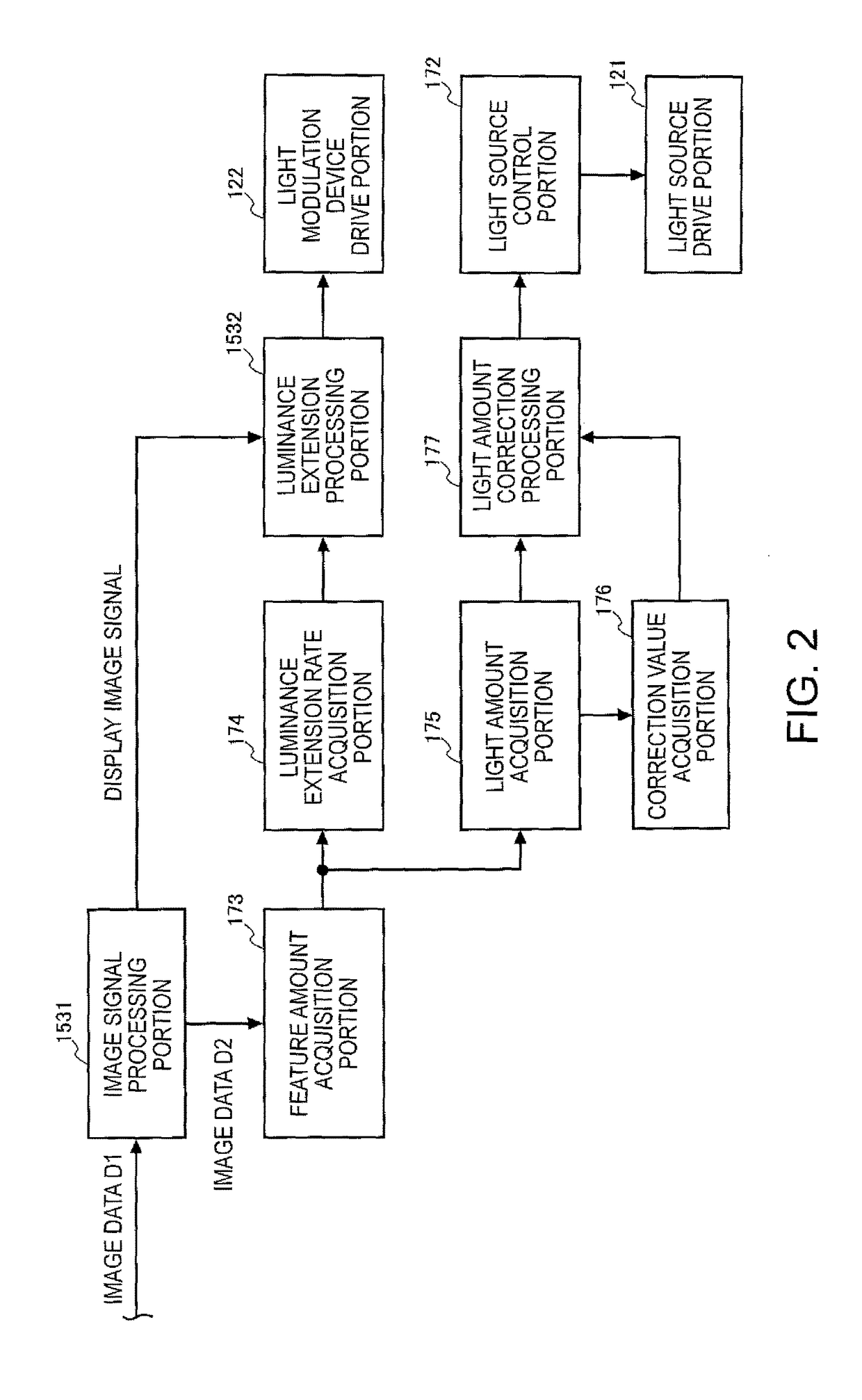
[0019]According to the aspect of the invention with this configuration, it is possible to correct the set amount of light that is acquired by the light amount acquisition portion by a coefficient corresponding to the increase characteristics or the decrease characteristics of the temperature of the light source. Therefore, it is possible to correct the set amount of light by using the correction value corresponding to the temperature characteristics of the light source and to appropriately control the amount of light that is output by the projector.
[0023]According to the aspect of the invention with this configuration, the correction value is set based on the average value of the set amount of light. Therefore, it is possible to set the correction value to an appropriate value by reducing an influence of a rapid variation in image data.
[0025]According to the aspect of the invention with this configuration, it is possible to perform the extension processing for extending the luminance range of the image data.
[0027]According to the aspect of the invention with this configuration, it is possible to acquire the correction value corresponding to the set amount of light from the storage portion. Therefore, it is possible to reduce time and effort for calculating the correction value.

Problems solved by technology

In this case, the amount of the light emitted by the projector is a brightness to which both the characteristics of the light source and a variation due to the dimming are applied, and the amount of light may be unstable.

Method used


Image

  • Projector and light source control method
  • Projector and light source control method
  • Projector and light source control method

Examples


first embodiment

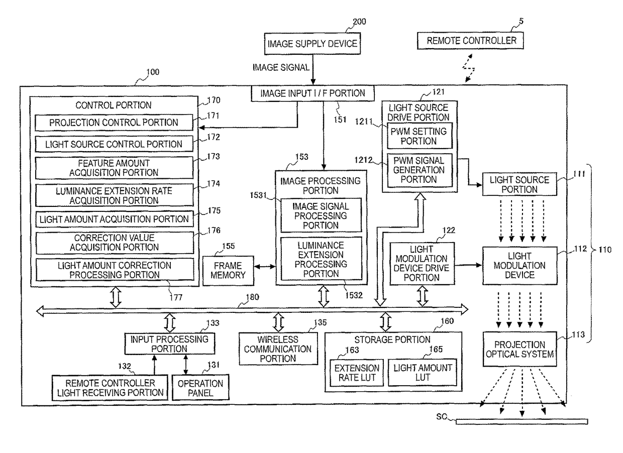
[0037]FIG. 1 is a block diagram illustrating a configuration of a projector 100 of the first embodiment.

[0038]The projector 100 is an apparatus that is connected to an external image supply device 200 such as a personal computer or various video players and projects an image video to a projection object based on an image signal supplied from the image supply device 200.

[0039]As the image supply device 200, it is possible to use a video output device such as a video reproducing device, a Digital Versatile Disk (DVD), a video tuner device, a set-top box of a Cable television (CATV), and a video game device, a personal computer, and the like.

[0040]In addition, a projection object may be an object that is not uniformly flat such as a building or an object, or may be an object having a flat projection surface such as a screen SC or a wall surface of a building. In the embodiment, a case of projecting on the screen SC of a plane is exemplified.

[0041]The projector 100 includes an image inp...

second embodiment

[0131]A projector 100 of a second embodiment will be described. Since the projector 100 of the second embodiment has the same configuration as that of the first embodiment, the description of the configuration of the second embodiment will be omitted.

[0132]A correction value acquisition portion 176 of the second embodiment uses a value that is set in advance as a correction value C(t) without calculation of the correction value C(t) in a case where predetermined conditions are satisfied. For example, if a light source portion 111 is turned off, a temperature of a light source is rapidly lowered and the correction value C(t) that is changed by the correction value acquisition portion 176 may not follow the temperature variation in the light source. In this case, if a light amount that applies a load to the light source is set, it becomes a cause of failure of the light source.

[0133]Therefore, in a case where the set light amount K(t) that is acquired by the light amount acquisition p...

third embodiment

[0134]A projector 100 of a third embodiment will be described. Since the projector 100 of the third embodiment has the same configuration as that of the first embodiment, the description of the configuration of the third embodiment will be omitted.

[0135]A black image is inserted between images and an image in which an image after insertion of the black image is gradually bright is included in an image displayed by the projector 100. The black image inserted between the images is inserted in a very short period of time. Therefore, an influence on the temperature characteristics of the light source is small. Therefore, it is not necessary to correct an output amount of light of the light source based on a luminance of only the black image.

[0136]Therefore, the correction value acquisition portion 176 of the third embodiment does not obtain the correction value C(t) using the set light amount K(t) that is input from the light amount acquisition portion 175 as it is and calculates an ave...


PUM


Abstract

A projector includes a light source portion; a light source control portion that controls an amount of light emitted by the light source portion; a feature amount acquisition portion that inputs image data and calculates an image feature amount of the input image data; an amount of light acquisition portion that acquires a set amount of light of the light source portion based on an image feature amount; a correction value acquisition portion that acquires a correction value based on the set amount of light; and an amount of light correction processing portion that corrects the set amount of light by using the correction value acquired by the correction value acquisition portion. The light source control portion controls the amount of light of the light source based on the set amount of light that is corrected by the amount of light correction processing portion.

Description

CROSS-REFERENCE[0001]The entire disclosure of Japanese Patent Application No. 2016-006183, filed Jan. 15, 2016 is expressly incorporated by reference herein.BACKGROUND[0002]1. Technical Field[0003]The present invention relates to a projector and a light source control method.[0004]2. Related Art[0005]In the related art, a projector performing dimming processing for controlling a brightness of light emitted from a light source according to a luminance of an image that is displayed is known (for example, see JP-A-2007-41535). An image display device of JP-A-2007-41535 calculates an image feature amount indicating features of the luminance of image data that is displayed, determines dimming coefficient controlling a dimming element based on the calculated image feature amount, and controls the dimming element based on the determined dimming coefficient.[0006]However, the amount of light emitted from the light source may vary due to an influence of a temperature or the like of the light...

Claims


Application Information

Patent Timeline
Patent Type & Authority Patents(United States)
IPC IPC(8): H04N5/74G03B21/26H04N9/31
CPCH04N9/3155H04N9/3194
Inventor NOBORI, TATSUHIKO
Owner SEIKO EPSON CORP
Learn More