Agricultural harvesting unit and method of harvesting using the unit

a harvesting unit and agricultural technology, applied in the field of agricultural harvesting, can solve the problems of user inconvenience, waste of valuable harvesting time, and inability to directly observe the front region of the harvesting system, and achieve the effect of facilitating the rearward progress of severed crops and facilitating severance of crops

Active Publication Date: 2017-12-26
CRARY INDS
View PDF10 Cites 1 Cited by
  • Summary
  • Abstract
  • Description
  • Claims
  • Application Information

AI Technical Summary

Benefits of technology

The invention is a harvester with a combine that can cut and collect crop as it moves over the ground. The harvester has a frame with a cutting assembly that can process the crop as it moves. The harvester also has a fluid delivery system that can change the volumes and direction of pressurized fluid to help the cutter and push the crop rearward for further processing. The control system of the harvester allows the user to adjust the fluid delivery system through an actuator. This invention provides an improved method for harvesting crop with a combine.

Problems solved by technology

However, seated in the cab, a user is unable to directly observe the front region of the harvesting system to determine whether a selected angle for the pressurized fluid streams and a particular flow volume is optimal.
This may have to be done multiple times, as a result of which valuable harvesting time may be wasted.
Further, a user is inconvenienced by potentially having to repeatedly enter the cab, depart the cab to inspect, and re-enter the cab before harvesting begins.
Aside from the inconvenience, a user has an increased likelihood of injury by reason of having to repeatedly enter and exit the cab by climbing over different structure on the head and combine below the elevated cab.
This is generally inconvenient and doubles necessary manpower at startup.
Thus, adjustments may have to be made periodically, as a result of which the user experiences the same inconvenience and loss of time and / or may inefficiently use manpower as discussed above.
The industry has continued to contend with the above problems because of a lack of any practical solution therefor.

Method used


Image

  • Agricultural harvesting unit and method of harvesting using the unit
  • Agricultural harvesting unit and method of harvesting using the unit
  • Agricultural harvesting unit and method of harvesting using the unit

Examples


Embodiment Construction

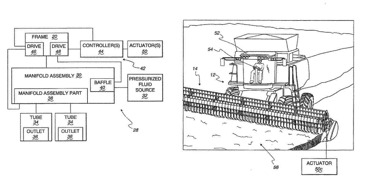
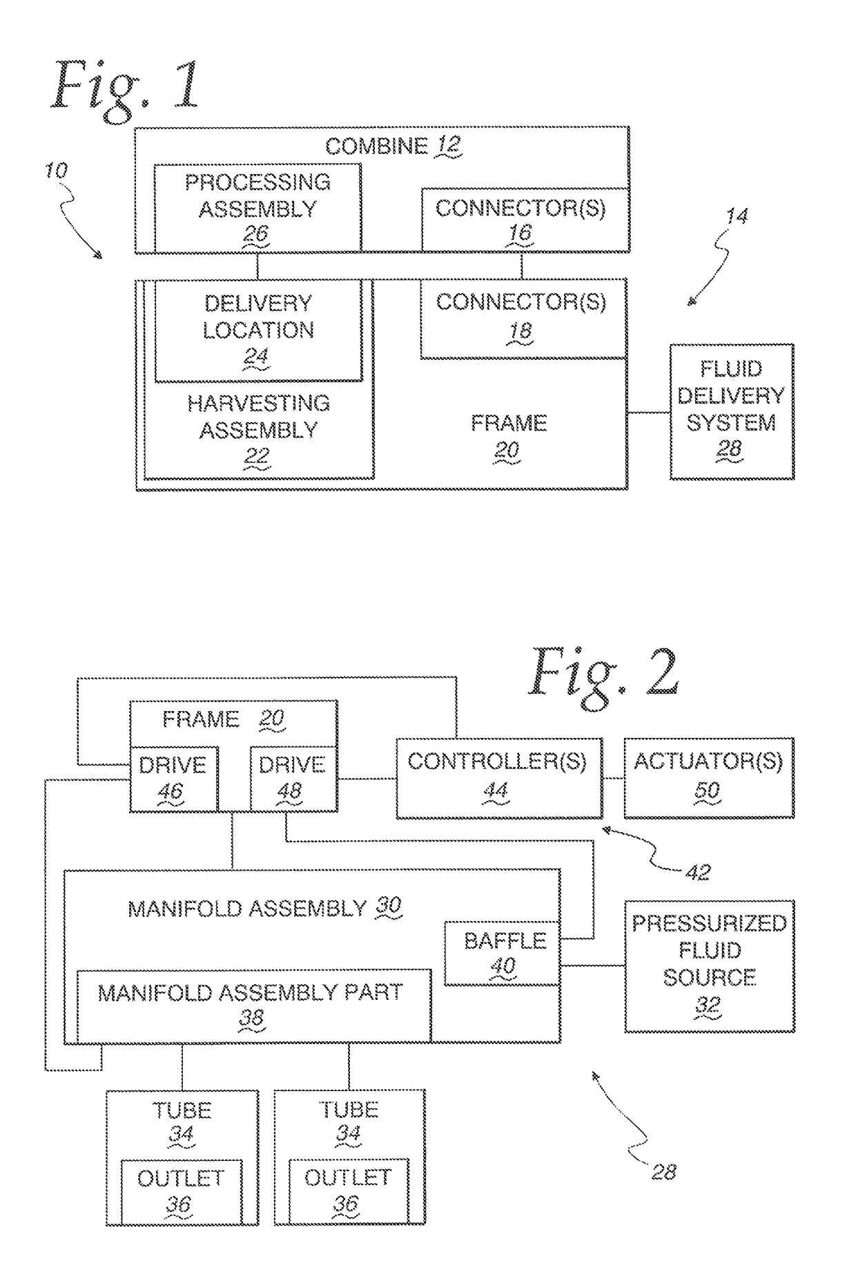
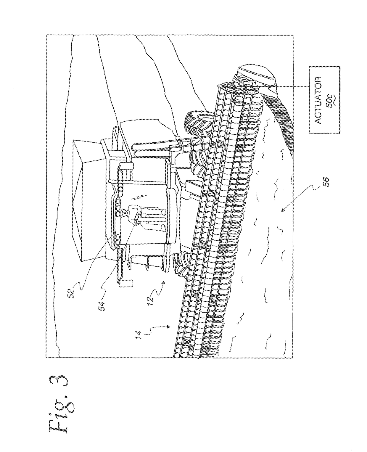
[0045]A harvesting unit, according to the invention, is shown schematically at 10 in FIG. 1. The harvesting unit 10 is made up of a combine 12, configured to be advanced over underlying terrain, and a harvesting apparatus at 14, configured to be advanced by the combine 12 over an area in which crop is grown. The harvesting apparatus 14 is commonly referred to as a “head” that may be releasably joined to the combine 12 through cooperating connectors 16, 18, respectively on the combine 12 and harvesting apparatus 14.

[0046]The harvesting apparatus 14 has a frame 20 that supports operating components for the harvesting apparatus 14. The frame 20 has laterally spaced sides, a front, and a rear.

[0047]A harvesting assembly 22 on the frame 20 is configured to process crop over a width between spaced sides of the frame 20 as it is advanced. The harvesting assembly 22 may be configured to: a) sever crop; and / or b) process pre-severed crop, as by controlled delivery to the combine 12.

[0048]The...


PUM


Abstract

A harvesting unit with a combine, having a user cab. A harvesting apparatus, advanced by the combine, has a frame and a harvesting assembly on the frame configured to process severed crop over a width between spaced sides of the frame. A fluid delivery system discharges pressurized fluid in discrete streams each directed to at least one of: a) facilitate severance of crop by the harvesting assembly; and b) facilitate advancement of severed crop rearwardly in relationship to the frame for further processing. A user can selectively vary at least one of: a) a volume of pressurized fluid; and b) a direction of pressurized fluid in the discrete streams. A control system has at least one actuator accessible and operable from outside of the cab through a user input to cause the at least one of the volume of pressurized fluid discharged, and direction of the pressurized fluid, in the discrete streams to be varied.

Description

BACKGROUND OF THE INVENTION[0001]Field of the Invention[0002]This invention relates to agricultural harvesting and, more particularly, to a harvesting unit utilizing a pressurized fluid to enhance crop processing.[0003]Background Art[0004]For decades, crop harvesting systems have utilized pressurized fluid to assist the processing of crops. A pioneer patent in this area—U.S. Pat. No. 4,936,082 entitled “Mechanical Air Reel”—discloses a basic arrangement of components that is common to most harvesting systems with a pressurized fluid assist capability.[0005]A harvesting “head”, as commonly coupled to a combine, typically consists of a frame that bounds a processing space within which severed crop is accumulated for delivery to the combine, whereat further processing occurs. The crop is severed at the front of the frame by stationary or moving cutting bars. Laterally spaced down tubes are arranged to deliver discrete, pressurized fluid streams in the vicinity of the cutting bars. The ...

Claims


Application Information

Patent Timeline
IPC IPC(8): A01D57/00A01D41/06A01D41/127A01D101/00
CPCA01D57/00A01D41/06A01D41/1274A01D2101/00A01D57/03A01D57/10
Inventor CAVKUSIC, DAMIRRICHARD, BENROSS, DANIELLEACH, MICHAELLEE, MITCHELL
Owner CRARY INDS
Why Eureka
Try Eureka