Foot prosthesis

a foot and prosthesis technology, applied in the field of foot prosthesis, can solve the problems of limited connection means and outward deflection of damping elements, and achieve the effects of simple stamping operation, easy manufacturing, and easy formation

Active Publication Date: 2017-12-19
OSSUR ICELAND EHF
View PDF17 Cites 2 Cited by
  • Summary
  • Abstract
  • Description
  • Claims
  • Application Information

AI Technical Summary

Benefits of technology

[0008]Because, according to the invention, the connecting means is guided by the damping element and thus by, so to speak, the center of rotation, the movement of the upper part relative to the lower part and thus the pivoting around the center of rotation is limited by this connecting means neither in the heel area, nor in the mid-foot area situated in front, nor in the area of the tip of the foot. As a result, the damping element can deflect inwardly and thus the upper part can pivot versus the lower part more-or-less around the center of rotation over a relatively wide range and without limitation, which means that the ability of the upper part to move relative to the lower part is considerably improved. The deflection distance is thus not limited as long as the springs are not in contact, which occurs at the end of the movement as the foot rolls over the tip. When the springs are in contact, i.e., when the upper part makes contact with the lower part, what can be called the “virtual center of rotation” migrates forward from the damping element to the contact point of the upper part with the lower part, and this connection tensions the upper part against the lower part, which leads in turn to a progressive increase in the force. There is therefore a considerable amount of relative mobility between the upper part and the lower part in the longitudinal direction of the foot, which is achieved in particular by the use of a single connecting means to couple the two parts, which connecting means passes through the damping element. In addition, there is also a contribution to be expected from the fact that the damping element is preferably not connected to the upper part, so that, in the extreme case, the upper part is able to move in the longitudinal direction of the foot relative to the damping element. It is prevented from being lifted off by the longitudinally strong connecting means.
[0009]Overall, the foot prosthesis according to the invention therefore makes it possible for the user to walk much more comfortably and in a manner closer to that possible with a real foot. The shear forces which occur in the anterior-posterior direction are not completely suppressed, because no cable and strap connections, as described above, are provided to limit the movement, as a result of which there are no abrupt interruptions in the rolling movement which can be perceived by the user.
[0014]A retaining element configured in this way is especially easy to manufacture in the form of a sheet-metal retaining plate. The corresponding opening in the retaining element, through which the loop passes, and the tabs can be easily formed by a simple stamping operation.

Problems solved by technology

It also has considerable tensile strength, however, which means that the outward deflection of the damping element is limited by the connecting means.

Method used


Image

  • Foot prosthesis
  • Foot prosthesis
  • Foot prosthesis

Examples


Embodiment Construction

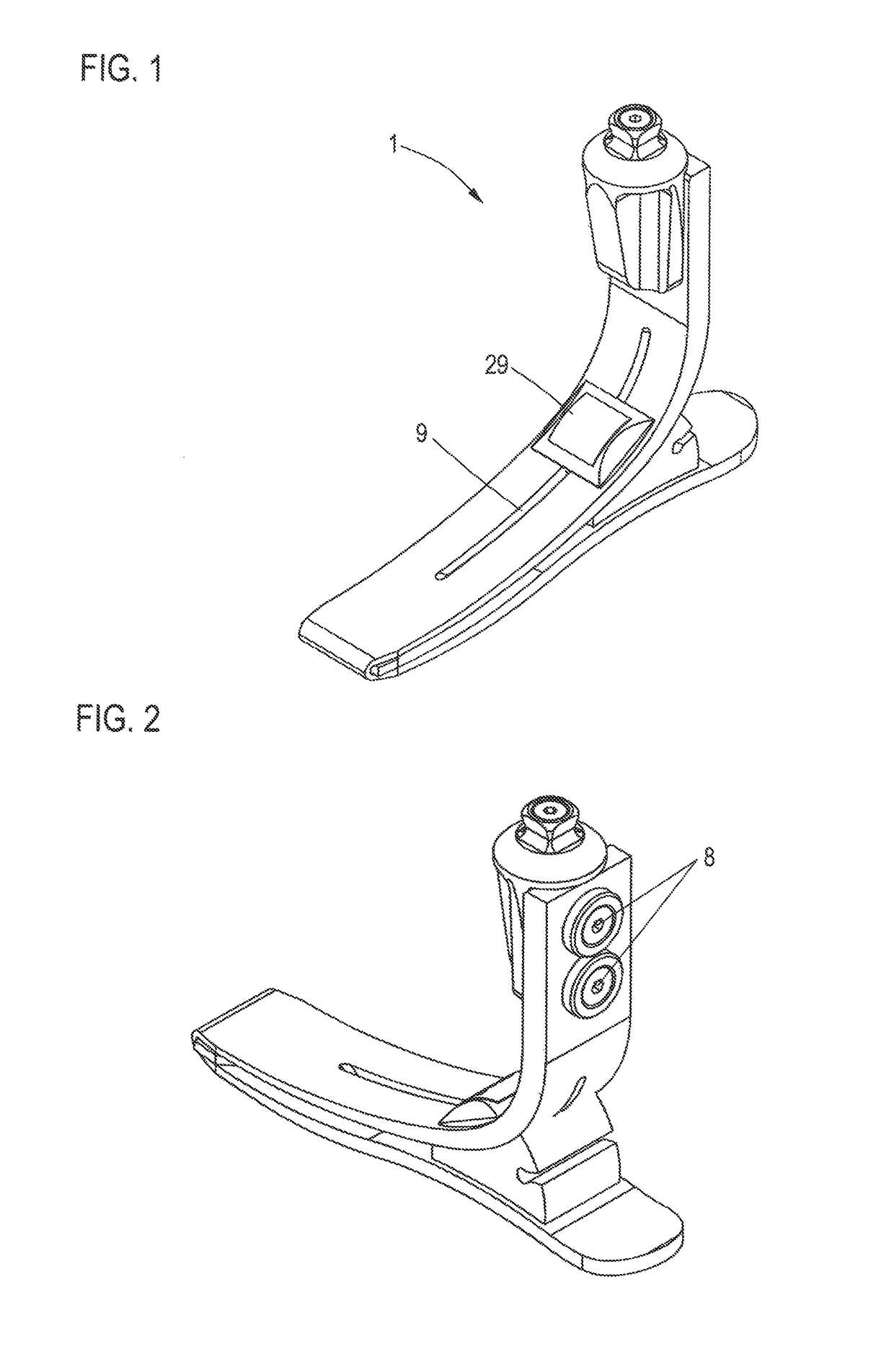
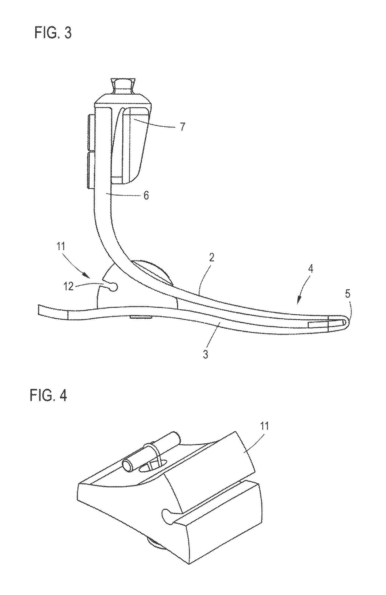
[0040]FIG. 1 shows a foot prosthesis 1 according to the invention, consisting of an upper part 2 and a lower part 3; see also FIGS. 2 and 3. The upper part 2 and the lower part 3 are realized by a one-piece component 4, wherein the upper part 2 and the lower part 3 are connected to each other in the area of the tip of the foot by a foldover 5. In this exemplary embodiment, the upper part 2 ends in a vertical section 6, on which a fastening means 7 is arranged for the connection of, for example, a prosthesis shaft by means of suitable mounting screws 8.

[0041]The component 4 is a one-piece component, preferably made of a carbon fiber composite material. This means that the upper part 2 and the lower part 3 can be formed in a single production step. As can be seen, the upper part 2 and the lower part 3, when seen from above, are congruent with each other, i.e., their outlines coincide.

[0042]An elongated slot 9 is provided in the upper part 2; this slot will be discussed again below. An...


PUM


Abstract

A foot prosthesis having an upper part and a lower part, which is set on the ground as the user walks, one part being arranged on top of the other a certain distance away. The two parts are connected to each other at the tip of the foot. The upper part and the lower part are formed by a one-piece component. In the area near the heel, an elastic damping element is arranged between the upper part and the lower part and is connected to the upper part and / or to the lower part. A compressible but longitudinally strong connecting element, which connects the upper part to the lower part, and which is guided through a recess in the damping element, is provided.

Description

CROSS-REFERENCE TO RELATED APPLICATIONS[0001]The present application claims priority of DE 10 2014 117 210.8, filed Nov. 25, 2014, the priority of this application is hereby claimed and this application is incorporated herein by reference.BACKGROUND OF THE INVENTION[0002]The invention pertains to a foot prosthesis.[0003]Many different types of foot prostheses are known. The goal of each foot prosthesis is to make the foot-fall as comfortable as possible, to cushion it on the basis of the elastic properties of the prosthesis, and to make it possible for the user to walk in a manner close to that in which one would walk with a real foot. One of the known foot prostheses comprises a lower part, which is set down on the ground when walking. Arranged on the lower part is an elastic damping element, which is arranged with an offset primarily toward the heel area. On this elongated damping element, a metal plate with a suitable fastening element such as a pyramid receiver is provided, on w...

Claims


Application Information

Patent Timeline
Patent Type & Authority Patents(United States)
IPC IPC(8): A61F2/50A61F2/66
CPCA61F2/66A61F2002/503A61F2002/6657A61F2002/5033A61F2002/6614A61F2002/5007
Inventor KRANNER, WERNEREPPENSTEINER, MAYNISSELS, VOLKERHERTWIG, JAN
Owner OSSUR ICELAND EHF
Why Eureka
Try Eureka