
Image display device and information input device

a display device and information input technology, applied in the field of image display devices and information input devices, can solve the problems of difficult controller operation, user wearing the head-mounted image display device is apt to perform an erroneous operation, and many limitations in design and manufacturing, and achieve the effect of accurate detection of user blinking

Inactive Publication Date: 2017-12-12
SONY CORP
View PDF17 Cites 5 Cited by
  • Summary
  • Abstract
  • Description
  • Claims
  • Application Information

AI Technical Summary

Benefits of technology

[0013]According to the technology which is disclosed in the present specification, it is possible to provide an excellent image display device and an information input device which are used by being mounted on a user's head portion, and are preferably operated based on movements of eyes of the user.
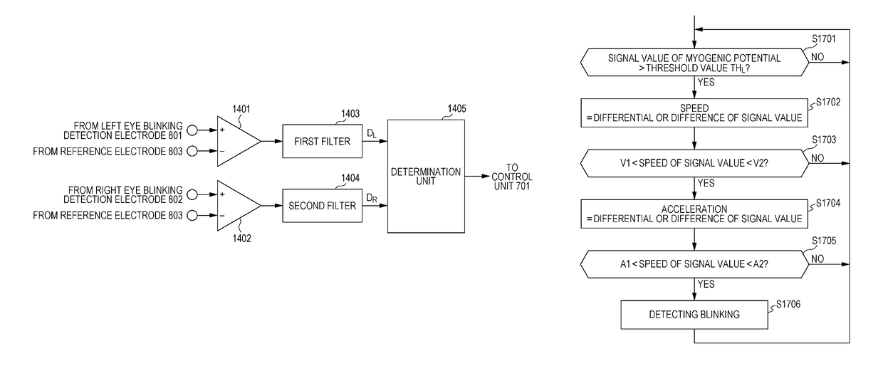
[0014]The image display device and the information input device to which the technology disclosed in the specification is applied are able to accurately detect blinking of a user based on a myogenic potential signal which is detected in the vicinity of the left and right eyes of a user wearing the device, and to perform a UI operation in which a hand is not used based on a combination of blinking on the left and right eyes.
[0015]Still other objectives, characteristics, and advantages of the technology which are disclosed in the specification will be clarified according to further detailed descriptions based on embodiments which will be described later, or accompanying drawings.

Problems solved by technology

However, a user wearing the head-mounted image display device is apt to perform an erroneous operation by fumbling for the controller, and treating the controller.
In particular, in a case of the head-mounted image display device of light shielding type, since a user is almost in a blindfolded state, it is difficult to operate the controller.
However, the line of sight input device should be provided so as not to be an obstruction in a field of vision in the head-mounted image display device, and there is much limitation in a design and manufacturing.
In addition, in particular, when it is a light shielding-type image display device, since an eyeball is photographed in an almost dark place, it is necessary to use a high sensitive camera when inputting a line of sight, and to perform high-definition image processing, accordingly, it results in an increase in cost of the device.

Method used


Image

  • Image display device and information input device
  • Image display device and information input device
  • Image display device and information input device

Examples


Embodiment Construction

[0042]Hereinafter, embodiments of the technology which is disclosed in the specification will be described in detail with reference to drawings.

[0043][A. Device Configuration]

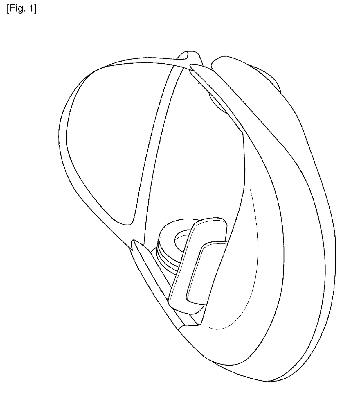
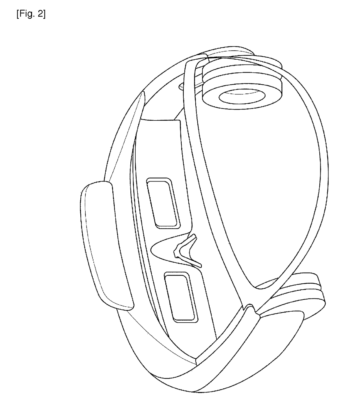
[0044]FIG. 1 illustrates a state in which an image display device according to an embodiment of the present technology is viewed from the front. In addition, FIG. 2 illustrates a state in which an image display device according to the embodiment of the present technology is viewed from the rear side. The illustrated image display device is a head-mounted structure body which is similar to a hat shape, and it is possible to mount the device by reducing a burden of a user by spreading a load of the device on the whole head portion even when a heavy load is concentrated in the front portion of a main body.

[0045]In addition, FIG. 3 illustrates a state in which the image display device according to the embodiment of the present technology is viewed from the side. The image display device according to the embodiment ...


PUM


Abstract

According to an illustrative embodiment, an information processing device is provided. The information processing device includes at least one electrode configured to generate at least one signal related to eye blinking of a subject; and a processing circuit configured to receive the at least one signal and detect eye blinking of the subject based on the at least one signal.

Description

CROSS-REFERENCE TO RELATED APPLICATION[0001]The present application is a national phase entry under 35 U.S.C. §371 of International Application No. PCT / JP2013 / 005380 filed Sep. 11, 2013, published on May 8, 2014 as WO 2014 / 068832 A1, which claims priority from Japanese Patent Application No. JP 2012-243065 filed in the Japanese Patent Office on Nov. 2, 2012.TECHNICAL FIELD[0002]A technology which is disclosed in the specification relates to an image display device which is used when a user wears the device at a head portion, and sees and hears an image, and an information input device by which a user performs an input operation by wearing the device. In particular, the technology relates to the image display device and the information input device which are operated based on eye movements of a user wearing the devices.BACKGROUND ART[0003]A head-mounted image display device which is used when seeing and hearing an image by wearing the device at a head portion, that is, a head-mounted...

Claims


Application Information

Patent Timeline
Patent Type & Authority Patents(United States)
IPC IPC(8): G09G5/00A61B5/0496A61B5/00A61B5/11G02B27/01G06F3/0482G06F3/01A61B5/0488A61B5/04A61B3/113
CPCG06F3/013A61B5/0488A61B5/0496A61B5/1103G02B27/01G06F3/0482A61B5/6814A61B5/04012A61B3/113A61B5/316A61B5/389A61B5/398A61B5/24
Inventor KITAZAWA, YUJIWADA, SEIJIAIZAWA, KOTAFUKUYAMA, YUTAKA
Owner SONY CORP
Learn More