Apparatus for conditioning of gases

a technology for apparatus and gases, applied in the direction of heating types, instruments, separation processes, etc., can solve the problems of known risk of sensitive parts of the pump, bearing point and/or sealing system being attacked by solid particles along with moisture present in the associated process gas, and achieve the effect of cost-effective operation and efficient separation

Active Publication Date: 2017-12-05
HYDAC PROCESS TECH
View PDF36 Cites 1 Cited by
  • Summary
  • Abstract
  • Description
  • Claims
  • Application Information

AI Technical Summary

Benefits of technology

This patent is about a new apparatus that condition gases by using a cyclone separator. This apparatus is low-maintenance, cost-effective, and efficient in separating gases. Additionally, the patent describes a sensor device that detects the amount of fluid in the apparatus and can control the output of the gas. This allows the system to operate automatically for longer periods of time. Overall, this patent provides an improved apparatus for conditioning gases that is easy to use and effective in separating gases.

Problems solved by technology

When handling corrosive process gases, for example, during pumping using turbo compressors, the known risk of sensitive parts of the pump, bearing points and / or sealing systems being attacked due to solid particles along with moisture present in the associated process gas exists.

Method used


Image

  • Apparatus for conditioning of gases
  • Apparatus for conditioning of gases
  • Apparatus for conditioning of gases

Examples


Embodiment Construction

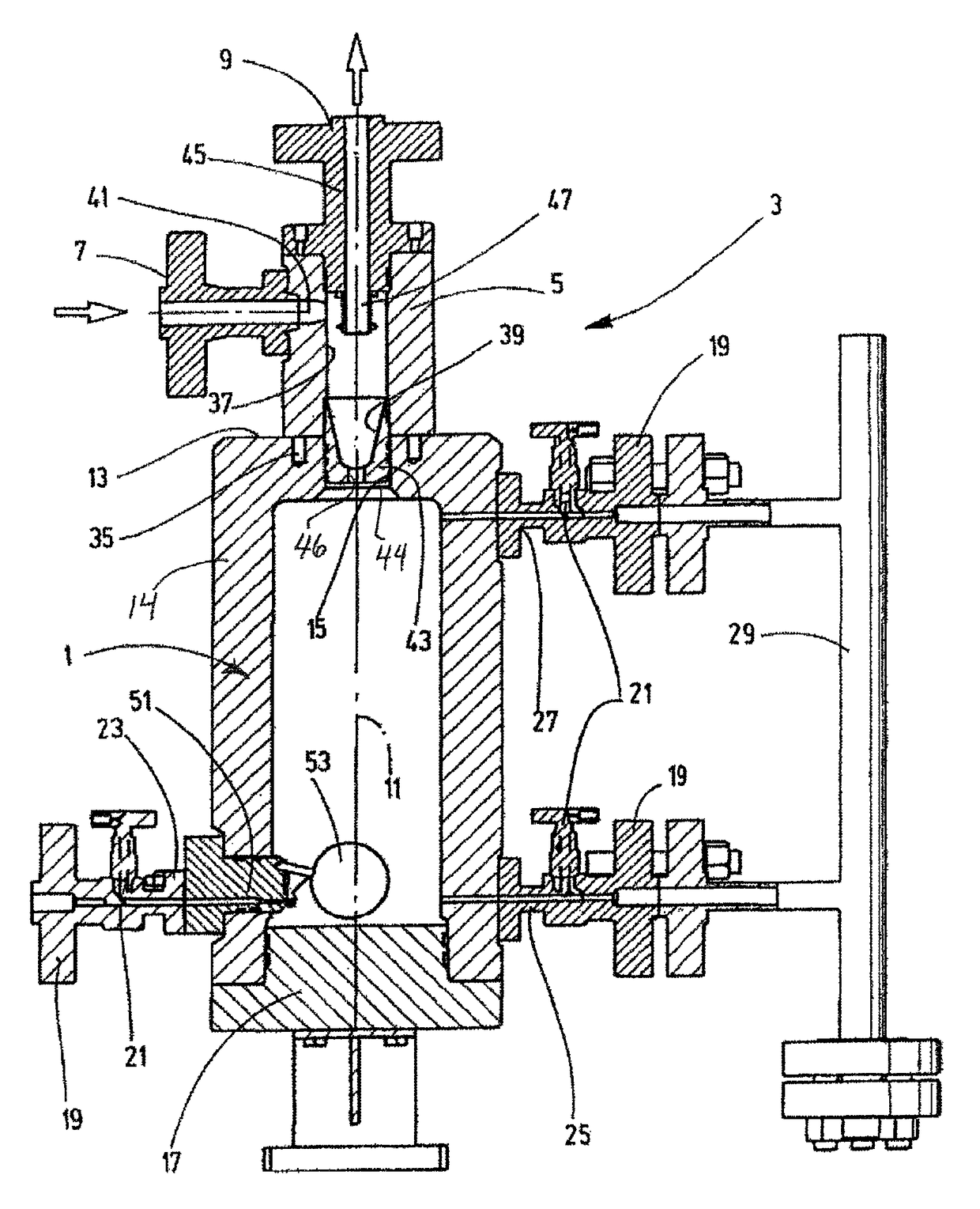
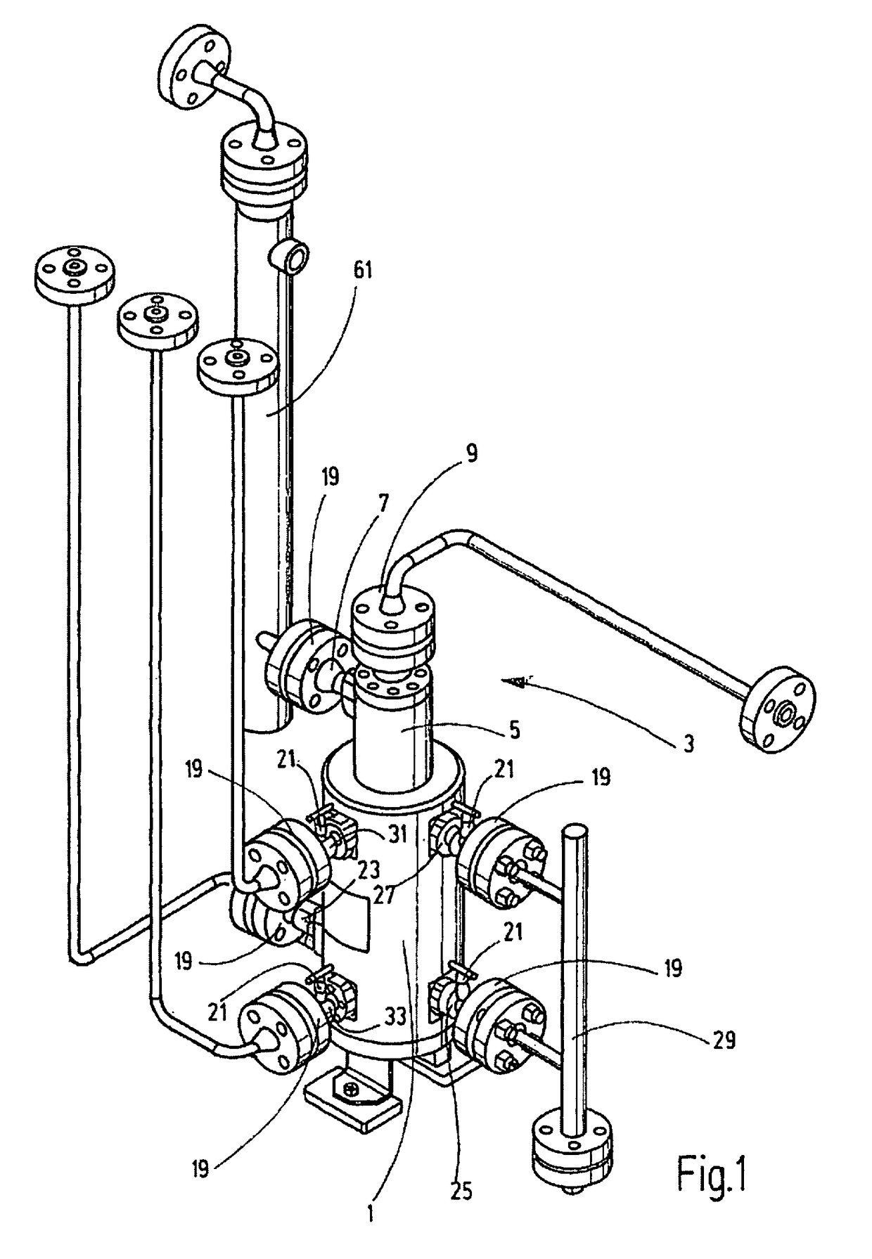
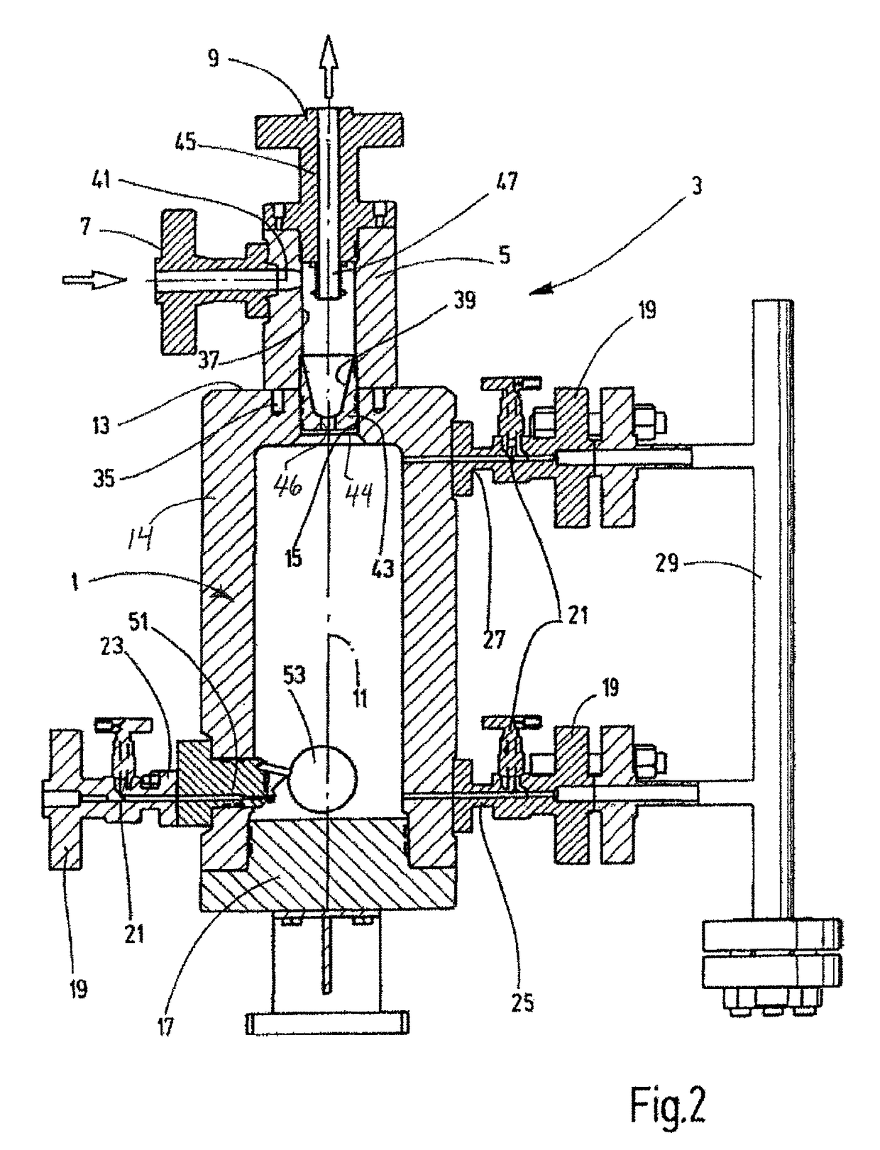
[0020]In FIG. 1, a collecting container 1 has a removable cyclone separator 3 mounted on the top thereof. Situated on the cyclone housing 5, shown in greater detail in FIG. 2, is an inflow connection or gas inlet 7 for the entry of the gas to be conditioned, and an outflow connection or gas outlet 9. The collecting container 1 is in the shape of a hollow cylinder having a vertical longitudinal axis 11. The cylinder is closed at its top by top or upper wall 13 located above in the drawing up to an inlet opening or central bore 15. The upper wall 13 extends inwardly and radially from the side wall 14 of the collecting container 1 relative to the longitudinal axis 14. The central bore 15 is radially spaced from the side wall 14 of the collecting container 1. The lower end is tightly sealed by a bottom piece 17. Collecting container 1 together with the bottom piece 17 exhibit a correspondingly high wall strength 1, for forming a pressure container for a high pressure level of greater th...


PUM

PropertyMeasurementUnit
Dimensionaaaaaaaaaa

Abstract

An apparatus for conditioning of gases, particularly sealing gas, includes a separator unit (3), particularly for separating liquids and / or particles from the gas flowing through the apparatus, and a collecting container (1) for the trapped substances. The separator unit (3) has a cyclone separator (3).

Description

FIELD OF THE INVENTION[0001]The invention relates to an apparatus for the conditioning of gases, in particular of sealing gas, comprising a separator unit for separating liquids and / or particles from the gas flowing through the apparatus, and comprising a collecting container for the trapped substances.BACKGROUND OF THE INVENTION[0002]Apparatuses of this kind are prior art. One area of application of such apparatuses is the conditioning of sealing gas. When handling corrosive process gases, for example, during pumping using turbo compressors, the known risk of sensitive parts of the pump, bearing points and / or sealing systems being attacked due to solid particles along with moisture present in the associated process gas exists. To counter this risk, sensitive parts, for example, the bearing points, must be protected by sealing gas in the form of a continuous flow of inert gas, with the inert gas flowing over the parts of the system to be protected. An appropriate inert gas may be dr...

Claims


Application Information

Patent Timeline
IPC IPC(8): B01D45/18B01D53/24B01D45/16B01D46/00B01D46/10B01D45/12
CPCB01D45/18B01D45/16B01D46/0005B01D46/10B01D53/24B01D46/0086B01D45/12B01D5/0021B01D5/0051B01D5/009B01D5/0096B01D53/265B01D53/266F24F3/14B01D2257/80G01F23/76G01F23/30G05D9/00
Inventor DEUTSCHMEYER, MANFREDSCHLICHTER, BERNHARDZELLER, SERGEJ
Owner HYDAC PROCESS TECH
Why Eureka
Try Eureka