Optical IQ modulator control

a technology of optical iq modulator and control arrangement, applied in the direction of digital transmission, transmission path sub-channel allocation, instruments, etc., can solve the problems of low noise monitor signal, implementation but has some severe disadvantages with respect to single sideband modulation

Active Publication Date: 2017-11-21
XIEON NETWORKS SARL
View PDF16 Cites 9 Cited by
  • Summary
  • Abstract
  • Description
  • Claims
  • Application Information

AI Technical Summary

Benefits of technology

[0035]The monitoring of the further pilot signals or the primary pilot signals (generated by MZM1 and MZM2) of the single sideband pilot signals output from MZM1 and MZM2 solves the problems of adjusting the parallel MZM1 and MZM2 including the automatic compensation of an imperfect modulator and modulator driver (especially imbalances in the transfer function for I and Q signal) properties and including power adjustment. Advantageously is the power minimum (bias point 0° in FIG. 1b) used for PTF adjustment. Alternatively a maximum at the double modulation frequency may be used.

Problems solved by technology

Misaligned modulators insert unwanted spurious by-signals into the optical waveform which distort the optical transmission.
Other problems which have to be solved in case of very high requirements on signal quality is to minimize the effects of the non perfect transfer functions of the analog modulator drivers and a not perfect balance, optical power and electro-optic transfer function within the IQ modulator.
The method described above for use with IQ modulation like (D)-QPSK is easy to implement but has some severe disadvantages with respect to single sideband modulation.
Another disadvantage of the method is the need for partial derivatives this implies low noise monitor signals and the absence of electrical disturbances by imperfect electrical analog and digital circuitry.

Method used


Image

  • Optical IQ modulator control
  • Optical IQ modulator control
  • Optical IQ modulator control

Examples


second embodiment

[0084]The second embodiment depicted in FIG. 4 uses a different kind of optical pilot signals PM1, PM2. These pilot signals are generated by electrical pilot modulation signals SM1, SM2 with a basic modulation frequency fco carrying different additional AF (audio frequency) carrier modulation signals M1, M2 with “carrier modulation frequencies” f1 and f2 (e.g. again f1=1.41 kHz, f2=1 kHz). The (electrical) modulation signals may even have identical basic modulation frequencies fco and generate therefore the pilot signals PM1 and PM2 with an optical first basic frequency fcw+fco and an optical second basic frequency fcw−fco also additional modulated by f1 and f2 respectively. ASK modulation or, with higher expenditure, each kind of “pilot signal modulation” may be used for the pilot signals. In FIG. 6 are only the relative basis frequency positions −fco and +fco of these modulated pilot signals indicated to avoid a confusing number of signals.

[0085]Corresponding to the embodiment of ...

first embodiment

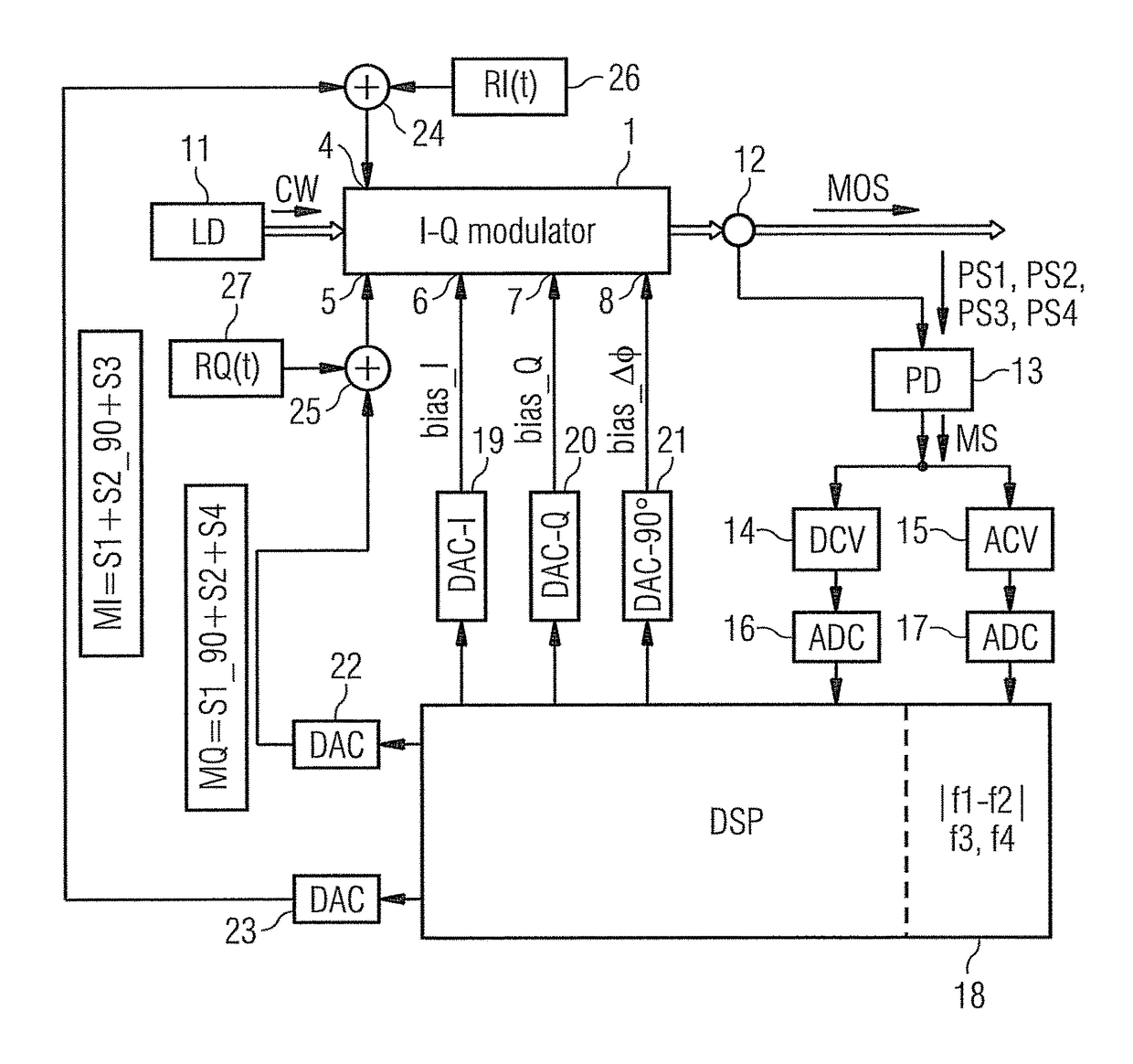
[0087]Hence, the standardized combined modulation signals MI and MQ (neglecting the amplitudes) for the first embodiment according FIG. 3 are

MI(t)=sin(2πf1*t)+cos(2πf2*t)+sin(2πf3*t)=S1+S2_90+S3;

MQ(t)=cos(2πf1*t)+sin(2πf2*t)+sin(2πf4*t)=S1_90+S2+S4.

[0088]The standardized combined modulation signals MI and MQ for the second embodiment using modulated pilot signals PM1, PM2 according FIG. 4 depend on the modulation format (neglecting the amplitudes) e.g. for ASK modulation with carrier modulation signals

M1=sin(2πf1*t) and M2=sin(2πf2*t):

MI(t)=sin(2πfc*t)*sin(2πf1*t)+cos(2πfc*t)*sin(2πf2*t)+sin(2πf3*t)=SM1+SM2_90+S3;

MQ(t)=cos(2πfc*t)*sin(2πf1*t)+sin(2πfc*t)*sin(2πf2*t)+sin(2πf4*t)=SM1_90+SM2+S4;

[0089]Power control signals CS3, CS4 (shown before adjustment as dashed lines in FIGS. 5 and 7) are derived from the further pilot signals PS3, PS4 and the phase shifters P1, P2 and P3, P4 are controlled by associated PTF bias (control) signals bias_I and bias_Q respectively till the output powe...


PUM

PropertyMeasurementUnit
frequencyaaaaaaaaaa
RIaaaaaaaaaa
RIaaaaaaaaaa

Abstract

An optical IQ modulator (IQM) including two parallel Mach-Zehnder modulators (MZM1, MZM2) generates single sideband data signals. A control unit (18) generates additional optical single sideband pilot signals (PS1, PS2) positioned in a lower and a higher sideband respectively, and also further pilot signals (PS3, PS4) in both sidebands. A IQ modulator output signal (MOS) converted into electrical monitoring signals (MOS) and monitored. A control unit (18) selects control signals (CS12, CS3, CS4) and controls the IQ modulator via its bias ports (6, 7, 8) till the power transfer functions (PTF) of the Mach-Zehnder modulators (MZM1, MZM2) and the phase difference (ΔΦ) between their output signals is optimized.

Description

FIELD OF THE INVENTION[0001]The invention relates to a method and an arrangement for controlling an optical IQ modulator.CROSS REFERENCE TO RELATED APPLICATIONS[0002]This application is a 35 U.S.C. 371 national stage filing of International Application No. PCT / EP2014 / 054021, filed on Mar. 3, 2014. The contents of the aforementioned applications are hereby incorporated by reference in their entireties.BACKGROUND OF THE INVENTION[0003]In optical transmission systems optical signals are transmitted over an optical fiber. Different kinds of modulation and associated types of modulators are used to generate appropriate transmission signals. A common modulator is the QAM (Quadrature Amplitude Modulation) or IQ modulator (I—in-phase, Q—quadrature). A common structure of such an IQ modulator is a nested MZM (Mach-Zehnder Modulator), which consist of two combined parallel working Mach-Zehnder modulators. Optical IQ modulators, independent of their respective realization, have to be adjusted ...

Claims


Application Information

Patent Timeline
Patent Type & Authority Patents(United States)
IPC IPC(8): H04B10/00H04L5/00H04B10/548H04B10/079H04B10/50G02F1/225G02F1/21
CPCG02F1/2255H04B10/07955H04B10/548H04L5/0048H04B10/50577G02F2001/212G02F1/212
Inventor GOTTWALD, ERICHROHDE, HARALD
Owner XIEON NETWORKS SARL
Why Eureka
Try Eureka