
Pressure actuated frack ball releasing tool

a technology of pressure actuation and releasing tools, which is applied in the direction of fluid removal, sealing/packing, and wellbore/well accessories. it can solve the problems of object being forced against, prior method has a drawback, and gravity is not much help in running in the replacement gun

Active Publication Date: 2017-11-07
BAKER HUGHES INC
View PDF17 Cites 13 Cited by
  • Summary
  • Abstract
  • Description
  • Claims
  • Application Information

AI Technical Summary

Benefits of technology

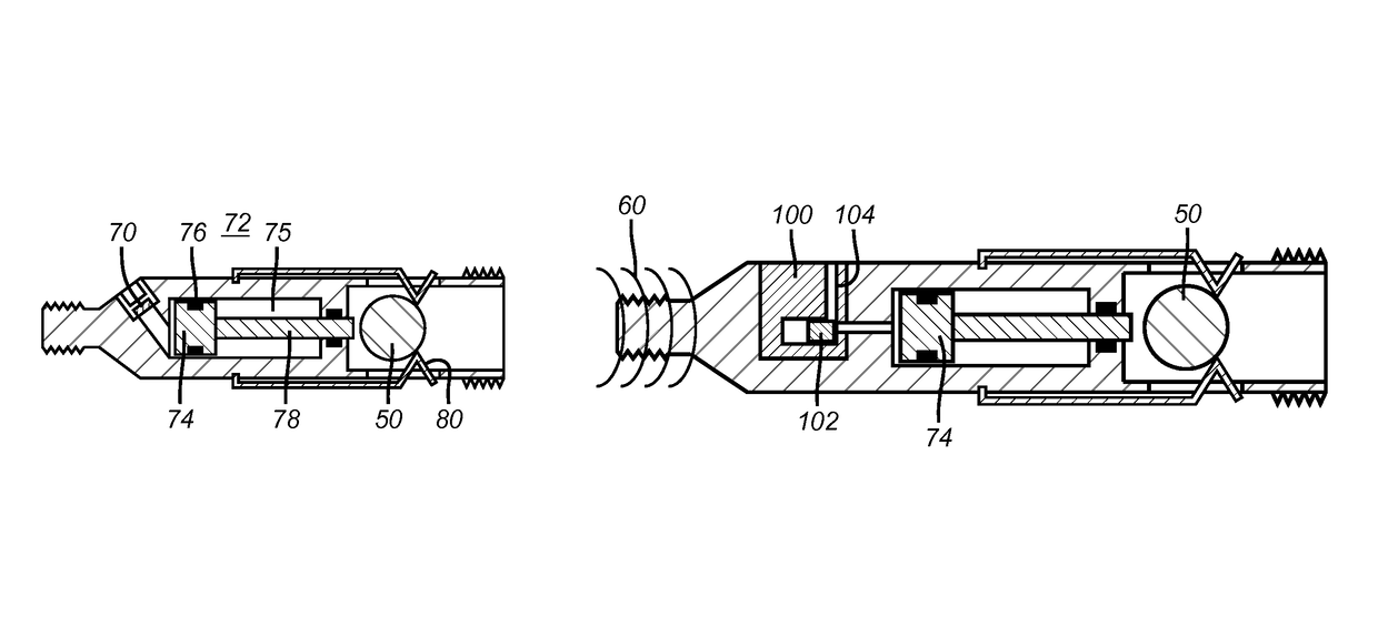
The patent describes a method of releasing an object that may block a passage in a device used in fracking, a process of extracting oil and gas from rocks. The object is introduced with the bottom hole assembly when the device is being set up. It is not released until the guns fire to create a pressure spike in the borehole that triggers the object retaining device to release the object. This method allows for larger objects and passages in the device to be used, even if the guns misfire. The device remains open and can be pumped in with new guns. Overall, this method ensures a safe and effective means of releasing objects during fracking operations.

Problems solved by technology

However, this prior method has a drawback if the guns misfire.
Thus, gravity is not much help in running in the replacement guns.
Furthermore, if the object was run in with the isolation device, then the object would be forced against the seat in the passage of the isolation device if any effort to use pressure or flow to deliver the replacement guns was employed.
The closing off of the passage in the isolation device means the replacement guns cannot be delivered on wireline with a pressure or flow assist and that alternative means such as coiled tubing or tractors have to be used to get the guns into position.
This adds enormous expense to the operation and creates issues of delay.
Even if the object is dropped after the misfired gun is removed, it still takes time to pump the object from the surface to the seat on the isolation device that is thousands of meters away costing time and additional fluid displacement.
There are many issues with this design.
A smaller passage in the isolation device could mean delays if a replacement gun has to be delivered with flow after an original gun misfires.
The spent perforating gun could also have burrs and sharp edges that could hang up or damage the object so badly that it might not seal at all when landing in the seat.

Method used


Image

  • Pressure actuated frack ball releasing tool
  • Pressure actuated frack ball releasing tool
  • Pressure actuated frack ball releasing tool

Examples


Embodiment Construction

[0030]FIGS. 1-6 illustrate a known way of doing a plug and perforate fracturing technique in a horizontal cemented production casing 10. FIG. 2 shows the BHA 12 in the desired location of the casing 10. The BHA 12 comprises perforating guns 14 followed by a setting tool 16 and a frack plug 18. The BHA 12 is run in on wireline 20. In FIG. 3 the setting tool 16 has set the frack plug 18 and released from the frack plug 18 so that the frack ball 22 is released. The wireline 20 provides power to the setting tool 16 which can be an E-4 setting tool sold by Baker Hughes Incorporated. The BHA 12 that is suspended by wireline 20 is aided in travelling into the horizontal portion of the well by pressure from the surface that creates flow to carry the BHA 12 into the horizontal portion of the borehole. At this time the frack plug is unset and flow can get past it and into an already perforated zone that is lower or into the formation if it is the initial zone to be perforated. The frack plug ...


PUM


Abstract

In a fracking context the object that will ultimately block a passage in an isolation device is introduced into the zone with the bottom hole assembly. The object is not released until the guns fire to create a pressure spike in the borehole that triggers the object retaining device to release the object. The retaining device is placed in close proximity to the isolation device and its setting tool to allow a larger object and passage in the isolation device to be used. If the guns misfire, the object is not released and comes out with the guns. The replacement guns can be pumped in because the passage in the isolation device has stayed open during the misfire. Direct and indirect object release in response to pressure created from the firing of the guns is contemplated.

Description

FIELD OF THE INVENTION[0001]The field of the invention is plug and perforate methods of sequential zone fracturing and more particularly devices and methods that allow retrieval of a frack plug occluding object designed to selectively plug an isolation device in the event the guns misfire and new guns need to be run in after the original guns are removed.BACKGROUND OF THE INVENTION[0002]In typical plug and perforate systems the bottom hole assembly (BHA) comprises an isolation device with a passage through it and a surrounding seat on the passage for an object to land on the seat and obstruct the passage. The object can be delivered with the isolation device or pumped to the isolation device after the perforating guns are shot and removed from the borehole with the setting tool for the isolation device. Delivering the object with the isolation device has the advantage of saving time to get the passage in the isolation device closed as compared to pumping down an object from the surf...

Claims


Application Information

Patent Timeline
Patent Type & Authority Patents(United States)
IPC IPC(8): E21B23/04E21B33/12E21B23/06E21B43/11
CPCE21B33/12E21B43/11E21B23/06E21B23/04E21B43/119E21B34/142
Inventor MAILAND, JASON C.MATTHEWS, DANIEL S.ROSENBLATT, STEVE
Owner BAKER HUGHES INC
Learn More