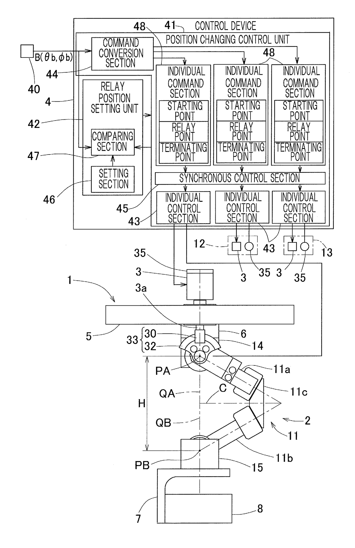
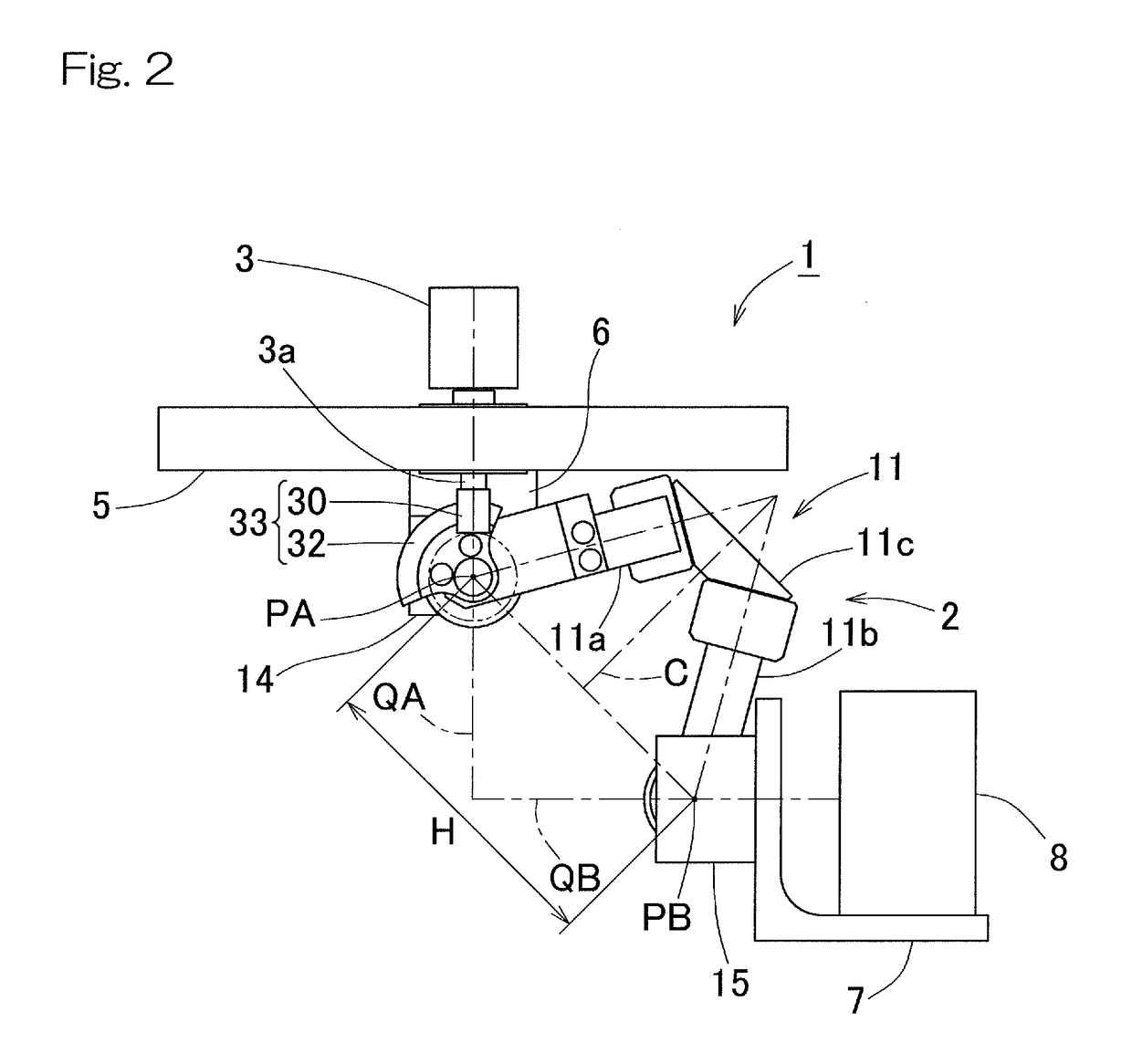
Linking apparatus control device
a control device and actuator technology, applied in the direction of electric programme control, program control, instruments, etc., can solve the problem of limited weight capacity of the travelling plate, and achieve the effect of reducing the weight of the end link member, good perforation process, and excellent mass-productivity
- Summary
- Abstract
- Description
- Claims
- Application Information
AI Technical Summary
Benefits of technology
Problems solved by technology
Method used
Image
Examples
second embodiment
[0152]The circumferential phase ε0 of the revolute pair portion T1 of the link mechanism 11 forming the reference has two mutually different solutions depending on the direction of assemblage of the proximal side end link members 11a to 13a relative to the proximal end side link hub 14. Accordingly, the positive or negative on the second line in the left side of the equation 1 and the positive or negative in the right side of the equation 2 are to be determined depending on the direction of assemblage of the proximal end side end links 11a to 13a relative to the proximal end side link hub 14. When the direction of assemblage is rightward direction, “+” is assigned, and when the direction of assemblage is leftward direction, “−” is assigned. By way of example, if the proximal side end link members 11a to 13a are assembled in the leftward direction as is the case with the second embodiment shown in FIG. 8, the equations 1 and the equation 2 are defined as the following equations 3 and...
fourth embodiment
[0157]FIGS. 15 and 16 illustrate the link actuator 1 designed in accordance with a This link actuator 1 is of such a design that each of the link mechanisms 11 to 13 of the link actuator main body 2 is of a rotational symmetrical type and the proximal end side end link 11a to 13a are assembled in the right direction relative to the proximal end side link hub 14. In the case of this link actuator 1, the positive or negative on the second line in the left side of the equation 1 and the positive or negative in the right side of the equation 2 represent “+” and are defined by the following equations 5 and 6. Using those equations 5 and 6, it is possible to control the actuator 3 and calculate the position of the distal end side link hub 15.
[0158](cos(γ / 2)cosɛ0sinαcosβnsinαsinβn)=(cos(ϕ-δn)-sin(ϕ-δn)0sin(ϕ-δn)cos(ϕ-δn)0001)(cos(θ / 2)0sin(θ / 2)010-sin(θ / 2)0cos(θ / 2))(cos(ϕ-δn)sin(ϕ-δn)0-sin(ϕ-δn)cos(ϕ-δn)0001)(cos(γ / 2)cosɛncos(γ / ...
fifth embodiment
[0159]FIGS. 17 to 19 illustrate a link actuator according to a This link actuator 1 is of such a design that as shown in FIG. 17, the proximal end side link hub 14 of the link actuator main body is disposed on a base bench 62 through a spacer 64. The link actuator main body 2 is of such a design that the proximal side end link members 11a to 13a are assembled in the leftward direction relative to the proximal end side link hub 14. For this reason, using the relational equations 3 and 4 discussed hereinbefore, the control of the actuator 70 as will be described later and the calculation of the position of the distal end side link hub 15 can be achieved.
[0160]As shown in FIGS. 18 and 19, the link actuator main body 2 is of such a design that the bearings 131 for rotatably supporting the end link members 11a to 13a and 11b to 13b relative to the proximal end side link hub 14 and the distal end side link hub 15 are rendered to be of an outer ring rotating type.
[0161]To describe, by way...
PUM
 Abstract
Description
Claims
Application Information
 - R&D
- Intellectual Property
- Life Sciences
- Materials
- Tech Scout
- Unparalleled Data Quality
- Higher Quality Content
- 60% Fewer Hallucinations
Browse by: Latest US Patents, China's latest patents, Technical Efficacy Thesaurus, Application Domain, Technology Topic, Popular Technical Reports.
© 2025 PatSnap. All rights reserved.Legal|Privacy policy|Modern Slavery Act Transparency Statement|Sitemap|About US| Contact US: help@patsnap.com


