
System and method to improve object tracking using multiple tracking systems

a tracking system and object technology, applied in the field of system and method for tracking objects, can solve the problems of instance-based tracking systems that lose track of objects, feature-based tracking systems that cannot track objects in subsequent images, and tracking systems that cannot distinguish objects from regions having a similar appearan

Active Publication Date: 2017-10-17
THE BOEING CO
View PDF16 Cites 0 Cited by
  • Summary
  • Abstract
  • Description
  • Claims
  • Application Information

AI Technical Summary

Benefits of technology

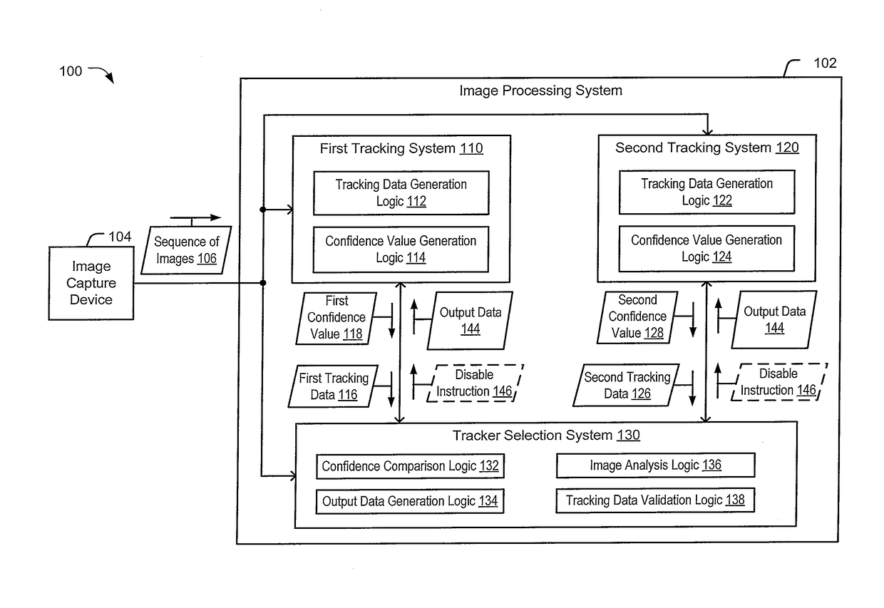
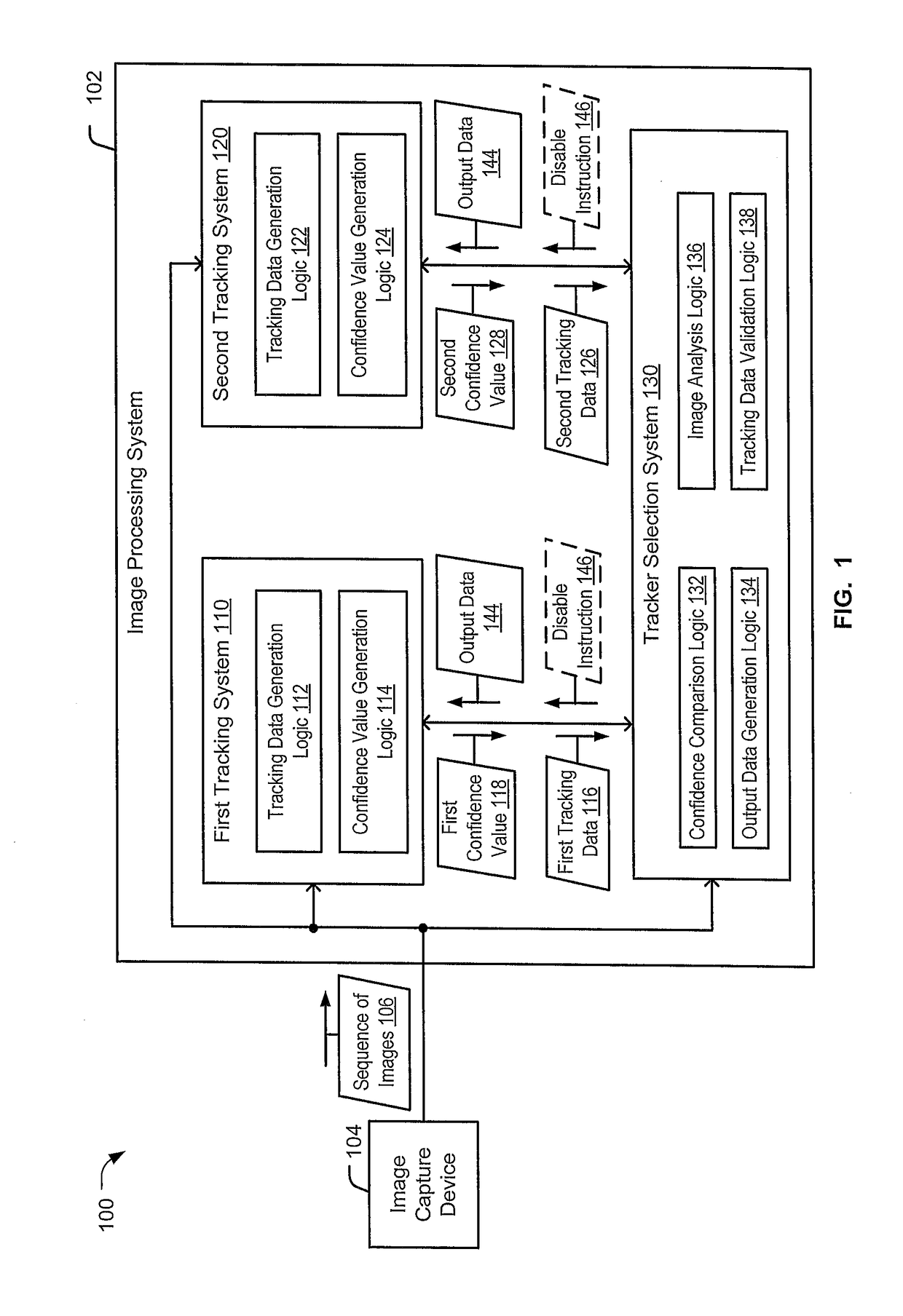
[0004]An image processing system includes a first tracking system, a second tracking system, and a tracker selection system (e.g., a “hybrid” tracking system). The first tracking system and the second tracking system are configured to track an object in a sequence of images. In a particular embodiment, the first tracking system is a feature-based tracking system and the second tracking system is an instance-based tracking system. The tracker selection system may receive first tracking data and a first confidence value from the first tracking system and may receive second tracking data and a second confidence value from the second tracking system. The first tracking data and the second tracking data may indicate locations of regions where the corresponding tracking system has tracked the object in an image. The tracker selection system may compare the confidence values, and based on a result of the comparison, the tracker selection system may provide output data including tracking data corresponding to the higher confidence value. The first tracking system and the second tracking system may use the output data, instead of their respective tracking data, to track the object in a subsequent image of the sequence of images. Thus, tracking data corresponding to a tracking system having a higher likelihood of success may be used by both tracking systems to track the object. In this manner, the tracker selection system may leverage the benefits of both the feature-based tracking system and the instance-based tracking system without experiencing the drawbacks associated with either of the tracking systems operating individually.
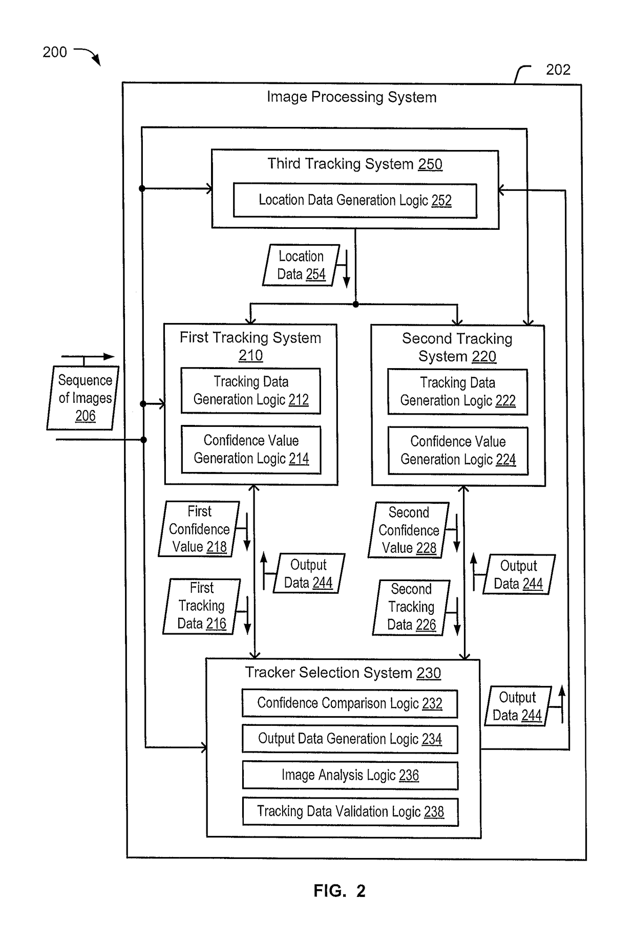
[0005]In a particular embodiment, the image processing system may include a third tracking system. The third tracking system may be a “lightweight” tracking system (e.g., the third tracking system may perform faster and using less processing resources but may be associated with a lower tracking accuracy than the first tracking system and the second tracking system). For example, the third tracking system may perform object tracking by comparing groups (e.g., “patches”) of pixels in different images to track the object. The third tracking system may run during time periods when the first tracking system and the second tracking system do not process images of the sequence of images. For example, the third tracking system may run during initialization time periods of the first tracking system and the second tracking system, or the third tracking system may run at a faster frame rate (e.g., the first tracking system and the second tracking system may process one out of every five images, but the third tracking system may process each image). The third tracking system may provide location data to the first tracking system and to the second tracking system to reduce a likelihood that the first tracking system and the second tracking system lose track of the object between processed images.
[0006]Additionally, the image processing system may include a sub-window tracking system. The sub-window tracking system may receive the output data from the tracker selection system and may determine a sub-window that is to be searched in a subsequent image based on the output data. The sub-window tracking system may provide sub-window data that indicates the sub-window to the first tracking system and to the second tracking system. The first tracking system and the second tracking system may search for the object in the sub-window of the subsequent image instead of in an entirety of the subsequent image. Reducing a search area of the subsequent image for the first tracking system and the second tracking system may increase speed and reduce power consumption of the first tracking system and the second tracking system.

Problems solved by technology

However, when the sequence of images has a low quality (e.g., a small number of pixels) or when the object lacks sufficient features to distinguish the object from the background pixels, the feature-based tracking system may be unable to track the object in the subsequent images.
Because the instances may indicate a difference between the object and surrounding regions when the object has relatively few features or when the sequence of images has a low quality (e.g., a small number of pixels), the instance-based tracking system may be able to track the object in subsequent images that are problematic for the feature-based tracking system.
However, when an image includes multiple regions that appear similar to the object, the instance-based tracking system may be unable to distinguish the object from a region having a similar appearance.
Additionally, when one or more characteristics of the object changes in the subsequent images, the instances may not be similar enough to the appearance of the object in the subsequent images, causing the instance-based tracking system to lose track of the object.
For example, IR images may be associated with a high failure rate at the first tracking system 110 (e.g., the feature-based tracking system) due to IR images having low quality and few features.
For example, the third tracking system 250 may have a high likelihood of losing track of the object after many images are processed.
For example, based on a determination that both the tracking data are invalid, the tracker selection system may not provide output data.
When both tracking data are invalid (e.g., neither tracking data is valid), output data corresponding to the image may not be provided, or may not include tracking data.

Method used


Image

  • System and method to improve object tracking using multiple tracking systems
  • System and method to improve object tracking using multiple tracking systems
  • System and method to improve object tracking using multiple tracking systems

Examples


Embodiment Construction

[0019]Particular embodiments of the present disclosure are described below with reference to the drawings. In the description, common features are designated by common reference numbers throughout the drawings.

[0020]The figures and the following description illustrate specific exemplary embodiments. It will be appreciated that those skilled in the art will be able to devise various arrangements that, although not explicitly described or shown herein, embody the principles described herein and are included within the scope of the claims that follow this description. Furthermore, any examples described herein are intended to aid in understanding the principles of the disclosure and are to be construed as being without limitation. As a result, this disclosure is not limited to the specific embodiments or examples described below, but by the claims and their equivalents.

[0021]Embodiments disclosed herein enable an image processing system that includes a first tracking system, a second t...


PUM


Abstract

A method includes receiving first tracking data and a first confidence value at a tracker selection system from a first tracking system. The method includes receiving second tracking data and a second confidence value at the tracker selection system from a second tracking system. The tracking systems may be configured to track an object in a sequence of images, and the first and second tracking data may indicate locations of regions where the corresponding tracking system has tracked the object in an image of the sequence of images. The confidence values may indicate likelihoods that a corresponding tracking system is tracking the object. The method further includes providing output data to the first tracking system and to the second tracking system. The output data may include data selected from the first tracking data and the second tracking data based on a result of a comparison of the confidence values.

Description

FIELD OF THE DISCLOSURE[0001]The present disclosure relates to a system and method for tracking an object in a sequence of images.BACKGROUND[0002]Tracking systems are configured to track a moving object in a sequence of images or video. One type of tracking system is a feature-based tracking system. The feature-based tracking system extracts feature data (e.g., data of “point features”) from a region in an image that includes object. The feature data includes data representing edges, corners, textures, size, or other aspects of the object that distinguish the object from background pixels. The extracted feature data is representative of the object, and the feature-based tracking system searches subsequent images of the sequence of images for regions that have similar feature data in order to track the object. When the sequence of images has a high quality (e.g., a high number of pixels) and when the object has sufficient features (e.g., texture, size, corners, etc.) to distinguish t...

Claims


Application Information

Patent Timeline
Patent Type & Authority Patents(United States)
IPC IPC(8): G06K9/00G01S5/16G06K9/62G06K9/32G06V10/25
CPCG01S5/16G06K9/00785G06K9/3233G06K9/6293G06V20/54G06V10/25G06F18/256
Inventor KIM, KYUNGNAMJEONG, CHANGSOOOWECHKO, YURI
Owner THE BOEING CO
Learn More