Eureka AIR delivers breakthrough ideas for toughest innovation challenges, trusted by R&D personnel around the world.

Devices, systems, and methods for peripheral arteriovenous fistula creation

a technology of arteriovenous fistula and peripheral arteriovenous vein, which is applied in the field of medical devices and methods, can solve the problems of long recovery time and not always provide a clear patient benefit, and achieve the effects of reducing neointimal proliferation, preventing tissue from protruding into the flow path of the fistula, and reducing bleeding of the tissue neighboring

Active Publication Date: 2017-10-10
EDWARDS LIFESCIENCES CORP
View PDF29 Cites 26 Cited by
  • Summary
  • Abstract
  • Description
  • Claims
  • Application Information

AI Technical Summary

Benefits of technology

[0008]In an alternative embodiment, energy is applied to the fistula, the energy selected from the group consisting of: electrical energy such as radio frequency or microwave energy; cryogenic energy; heat; radiation; and combinations thereof. In another alternative embodiment, an agent is delivered to the fistula, such as an agent selected from the group consisting of: anti-proliferatives; anti-biotics; antithrombogenics; and combinations thereof. In another embodiment, a flow rate is measured prior to or after the creation of the fistula. Based on the results of the measurement, the fistula creation procedure and / or a fistula modification procedure is adjusted to optimize the therapeutic benefit of the procedure and / or reduce risks or adverse events of the procedure.
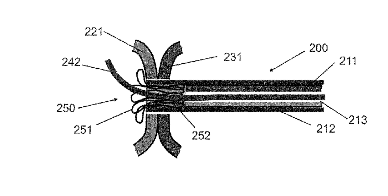
[0011]The method of the present invention preferably utilizes a peripheral artery selected from the group consisting of axillary; brachial; ulnar; radial; profundal; femoral; iliac; popliteal and carotid. The method of the present invention preferably utilizes a peripheral vein selected from the group consisting of saphenous; femoral; iliac; popliteal; brachial; basilica; cephalic; medial forearm; medial cubital; axillary; and jugular. The resultant fistula may have a circular or an oval cross-section, such as an oval cross-section that has a major axis greater than the diameter of either the artery or vein of the fistula. The method of the present invention preferably utilizes an anastomotic implant placed between the two vessels such as an implant which provides one or more of the following functions: scaffolding an opening between the first vessel and the second vessel; reducing neointimal proliferation into the fistula flow path; preventing tissue from protruding into the fistula flow path; placing a portion of the first vessel wall in tension with the tissue of the second vessel wall; reducing bleeding of the tissue neighboring the fistula; enhancing healing of the tissue neighboring the fistula; and combinations thereof. In a preferred embodiment, the anastomotic implant includes an active agent, and may also include a covering or partial covering.
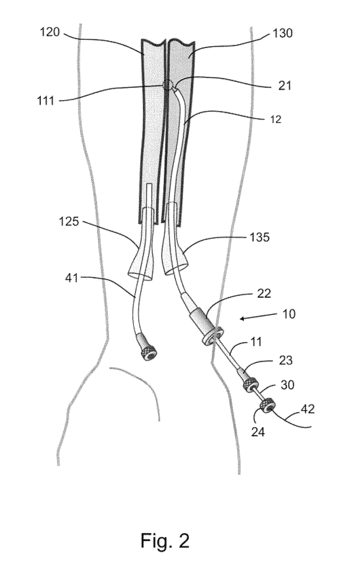
[0014]In yet another preferred embodiment, the method further comprises the placement of a guidewire from the first anatomical structure to the second anatomical structure, such as from an artery to a vein or a vein to an artery. This guidewire can be used to create or modify the fistula utilizing standard interventional “over-the-wire” techniques. In a preferred embodiment, the fistula is dilated to improve flow. In another preferred embodiment, an anastomotic implant is placed within the fistula, such as an implant that is dilated after placement. In yet another preferred embodiment, a second anastomotic implant is placed within the fistula, such as within all or a portion of the first anastomotic implant. In yet another preferred embodiment, energy or an active agent is applied to the fistula to improve the therapeutic benefit and / or enhance long-term effectiveness.
[0017]The method of the present invention preferably utilizes a peripheral artery selected from the group consisting of axillary; brachial; ulnar; radial; profundal; femoral; iliac; popliteal and carotid. The method of the present invention preferably utilizes a peripheral vein selected from the group consisting of saphenous; femoral; iliac; popliteal; brachial; basilica; cephalic; medial forearm; medial cubital; axillary; and jugular. The resultant fistula may have a circular or an oval cross-section, such as an oval cross-section that has a major axis greater than the diameter of either the artery or vein of the fistula. The method of the present invention preferably utilizes an anastomotic implant placed between the two vessels such as an implant which provides one or more of the following functions: scaffolding an opening between the first vessel and the second vessel; reducing neointimal proliferation into the fistula flow path; preventing tissue from protruding into the fistula flow path; placing a portion of the first vessel wall in tension with the tissue of the second vessel wall; reducing bleeding of the tissue neighboring the fistula; enhancing healing of the tissue neighboring the fistula; and combinations thereof. In a preferred embodiment, the anastomotic implant includes an active agent, and may also include a covering or partial covering.

Problems solved by technology

It can be used on only a small percentage of the total patient population, requires long recovery times, and does not always provide a clear patient benefit.

Method used


Image

  • Devices, systems, and methods for peripheral arteriovenous fistula creation
  • Devices, systems, and methods for peripheral arteriovenous fistula creation
  • Devices, systems, and methods for peripheral arteriovenous fistula creation

Examples


Embodiment Construction

[0037]Reference will now be made in detail to the present embodiments of the invention, examples of which are illustrated in the accompanying drawings. Wherever possible, the same reference numbers will be used throughout the drawings to refer to the same or like parts.

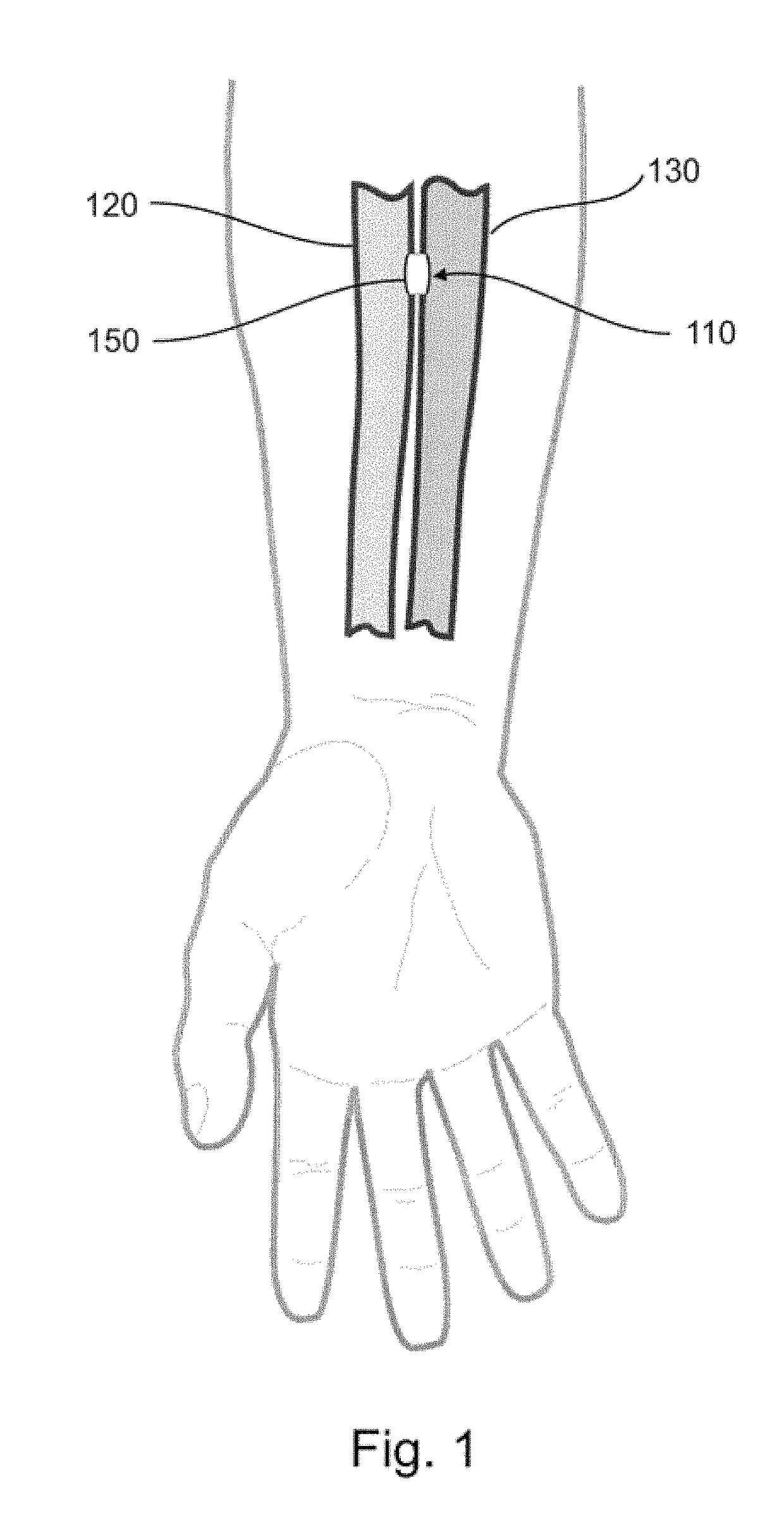
[0038]FIG. 1 depicts a peripheral arteriovenous fistula, fistula 110, created in a patient, such as a human or other animal, between artery 130 and vein 120. Fistula 110 is located in the patient's forearm and provides oxygenated blood from the higher-pressure arterial system to the venous system such that blood flows from the artery 130 to vein 120 through and fistula 110. The fistula may be created in one or more of a set of numerous locations in the body of the patient, preferably in a limb to avoid unnecessary trauma and risk to a major, central vessel such as the Aorta and Vena Cava. Applicable arteries for fistula 110 include but are not limited to: axillary; brachial; ulnar; radial; profundal; femoral; iliac; p...


PUM


Abstract

Devices, systems and methods are disclosed for the formation of an arteriovenous fistula in the limb of the patient. Embodiments include an apparatus for the creation, modification and maintenance of a fistula, including the modification of an existing dialysis fistula; and a method of supplying oxygenated blood to the venous circulation of a patient. A kit of anastomotic implants is described which supports a broad base of patient anatomies and fistula locations. The devices, systems and methods can be used to treat patients with one or more numerous ailments including chronic obstructive pulmonary disease, congestive heart failure, hypertension, hypotension, respiratory failure, pulmonary arterial hypertension, lung fibrosis and adult respiratory distress syndrome.

Description

CROSS-REFERENCE TO RELATED APPLICATIONS[0001]The present application is a continuation of U.S. patent application Ser. No. 12 / 017,437, filed Jan. 22, 2008, which is a continuation of PCT / US06 / 29081, filed Jul. 26, 2007, which claimed the priority of U.S. provisional application No. 60 / 702,777, filed on Jul. 26, 2005, the full disclosures of which are incorporated herein by reference.BACKGROUND[0002]1. Field of the Invention[0003]The present invention relates generally to medical devices and methods. More particularly, the present invention relates to devices and methods for creating or modifying a flow of oxygenated blood into the venous system of a patient.[0004]Chronic obstructive pulmonary disease affects millions of patients in the United States alone. The present standard of care is oxygen therapy, which requires a patient to remain near a stationary oxygen source or carry a bulky oxygen source when away from home or a treatment facility. It is easy to appreciate that such oxyg...

Claims


Application Information

Patent Timeline
Patent Type & Authority Patents(United States)
IPC IPC(8): A61M1/36A61B17/11A61M39/02A61B17/10A61B17/3205A61B17/00A61B17/08
CPCA61M1/3655A61B17/11A61M39/0247A61B17/083A61B17/10A61B17/32053A61M2039/0279A61B2017/1107A61B2017/1139A61M2039/0258A61M2039/0273A61M2039/0276A61B2017/00867
Inventor BRENNEMAN, RODNEYSCHAEFER, DEAN A.FLAHERTY, J. CHRISTOPHER
Owner EDWARDS LIFESCIENCES CORP
Why Eureka
Eureka Blog
Learn More