Input device
a technology of input device and display unit, which is applied in the direction of instruments, navigation instruments, and details of portable computers, can solve the problems of unintended input (wrong operation) of the display unit, and achieve the effect of preventing unintended input by the user
- Summary
- Abstract
- Description
- Claims
- Application Information
AI Technical Summary
Benefits of technology
Problems solved by technology
Method used
Image

Examples
first embodiment
[0032](First Embodiment)
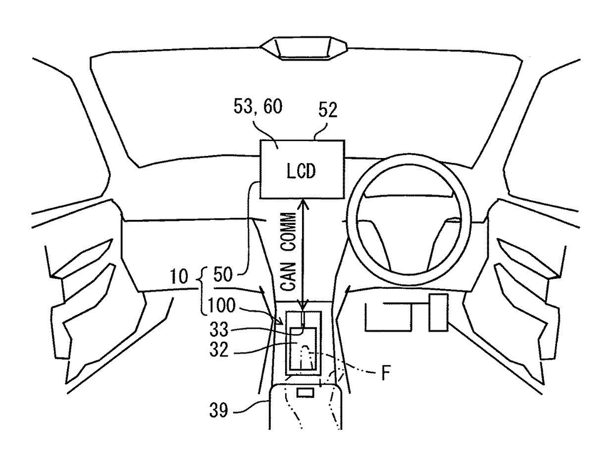
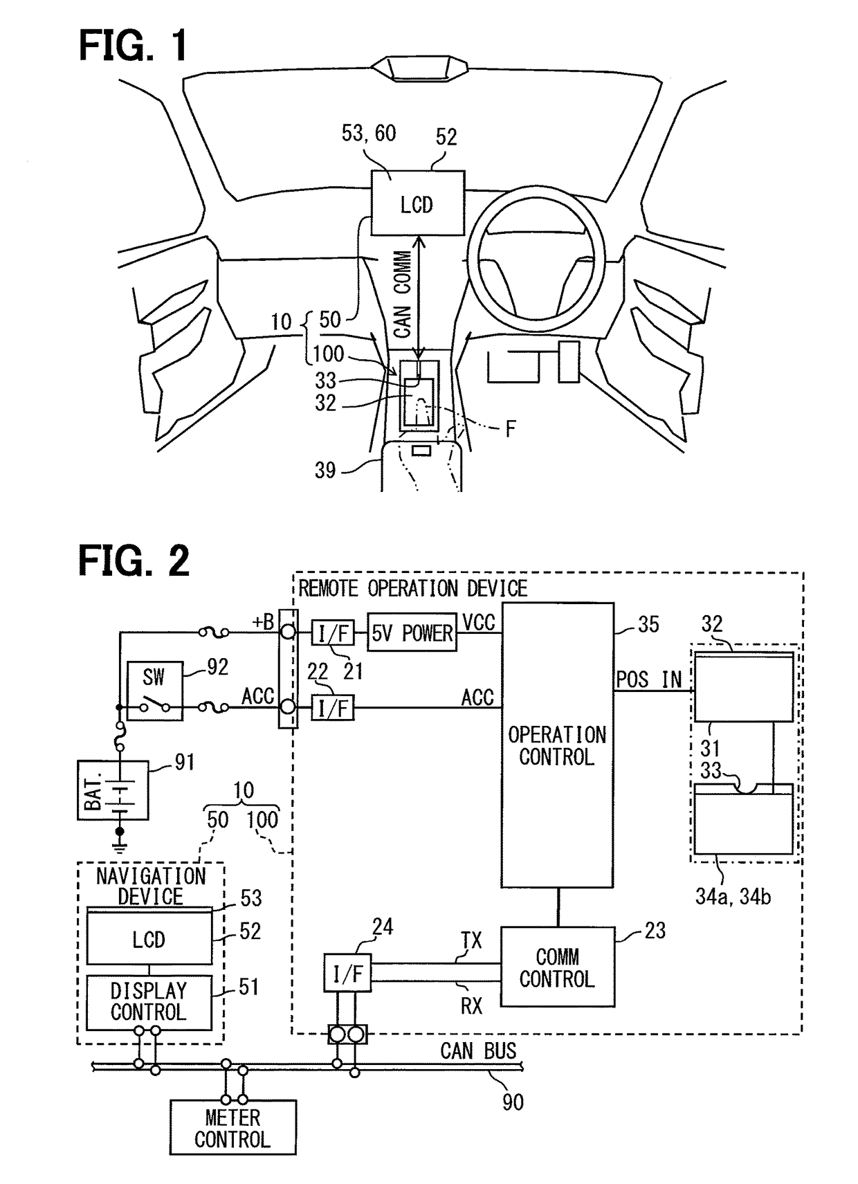
[0033]A first embodiment (FIG. 1 to FIG. 9) applies the input device of the present disclosure to a remote operation device 100 used to operate a navigation device 50. The remote operation device 100 is mounted in a vehicle, and constitutes a display system 10 in cooperation with the navigation device 50.
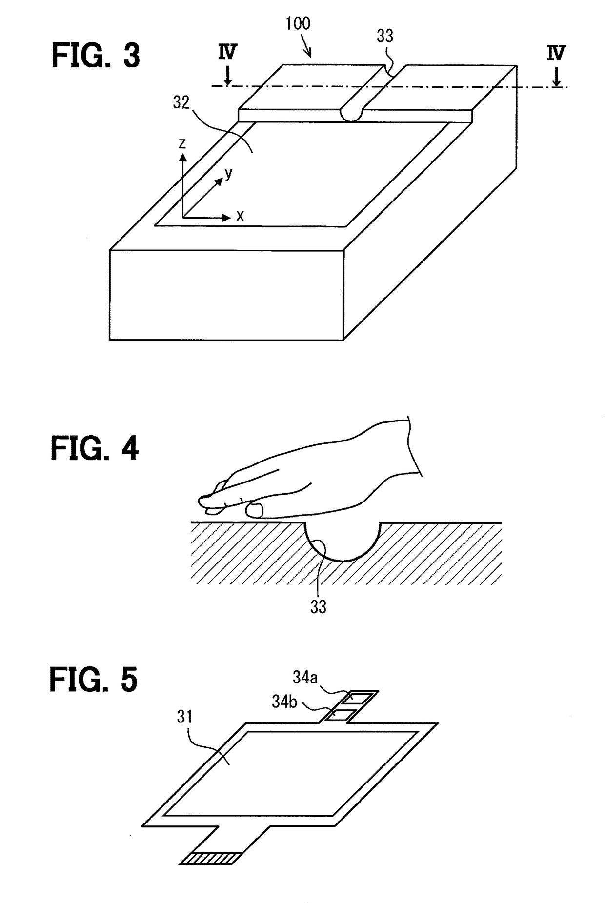
[0034]As illustrated in FIG. 1, the remote operation device 100 is installed in a position adjoining a palm rest 39 in a center console of the vehicle, and exposes its operation surface 32 within the easy reach of an operator (it is a user and assumed as a driver here). The remote operation device 100 includes a touch sensor 31 (FIG. 2 and FIG. 3), and the surface of the touch sensor 31 provides the above-described operation surface 32 to which an operator's finger operation is performed. F in FIG. 1 refers to the operator's finger.
[0035]The navigation device 50 is installed in the center of the right and left direction (the width direction of the vehicle) of...
second embodiment
[0089](Second Embodiment)
[0090]A remote operation device 100A according to a second embodiment is illustrated in FIG. 10 to FIG. 13. The second embodiment is different from the first embodiment in that the second embodiment further includes an input process associated with the display image 60 and directed to both a driver in a driver's seat and a front passenger in a front passenger's seat as an operator.
[0091]As illustrated in FIG. 10, FIG. 11, and FIG. 13, the remote operation device 100A is provided with multiple grooves (two grooves in the present case) formed side by side in the right-to-left direction. The two grooves are a driver's seat-specific groove 33a and a front passenger's seat-specific groove 33b.
[0092]The driver's seat-specific groove 33a is located on the driver side (right-hand side) portion of the remote operation device 100A, and is associated as a groove specific for the driver. The driver's seat-specific groove 33a is provided with a first sensor 34a1 and a s...
third embodiment
[0105](Third Embodiment)
[0106]A remote operation device 100B according to a third embodiment is illustrated in FIG. 14 to FIG. 17. The third embodiment in different from the first embodiment in that the third embodiment is further provided with multiple grooves (a navigation-specific groove 331, an audio-specific groove 332, an air conditioner-specific groove 333) and that the third embodiment is further provided with a select function of the image (for example, multiple main images of the first hierarchy level among multiple hierarchy levels) to be displayed according to the finger operation to each groove.
[0107]As illustrated in FIG. 14, FIG. 15, and FIG. 17, the remote operation device 100B is provided with multiple grooves (three grooves in the present case), that is, the navigation-specific groove 331, the audio-specific groove 332, and the air conditioner-specific groove 333, which are formed side by side in the right-to-left direction.
[0108]The navigation-specific groove 331 ...
PUM
 Abstract
Description
Claims
Application Information
 - R&D
- Intellectual Property
- Life Sciences
- Materials
- Tech Scout
- Unparalleled Data Quality
- Higher Quality Content
- 60% Fewer Hallucinations
Browse by: Latest US Patents, China's latest patents, Technical Efficacy Thesaurus, Application Domain, Technology Topic, Popular Technical Reports.
© 2025 PatSnap. All rights reserved.Legal|Privacy policy|Modern Slavery Act Transparency Statement|Sitemap|About US| Contact US: help@patsnap.com