
Ratchet tool

a ratchet and tool head technology, applied in the field of hand tools, can solve the problems of affecting the working efficiency, prone to damage to the screw head, and strong wobbling of the shaft, and achieve the effect of convenient use and simple structur

Active Publication Date: 2017-09-26
HANGZHOU GREAT STAR TOOLS +1
View PDF36 Cites 5 Cited by
  • Summary
  • Abstract
  • Description
  • Claims
  • Application Information

AI Technical Summary

Benefits of technology

The design reduces shaft wobble, enhances torque transfer efficiency, and reduces the turning force required when reversing, while providing a lighting feature for improved operation in various environments.

Problems solved by technology

Obviously, both methods have inconveniences, which affect working efficiency, and the screw head is also prone to damage.
1. The axle hole in the pawl sleeve and the axle section on the pawl seat extending forward into the axle hole are adopted to cooperate with each other, resulting in a small cooperating area of the shaft and the pawl base, strong wobbling of the shaft relative to the pawl seat, and poor performance of screwing a screw.
2. The number of teeth engaged between the pawl and the pawl sleeve is small, and the capacity of transferring torque is weak.
3. The number of the teeth of the ratchet is small, and the turning force required during turning back is large, so that the ‘directional’ feature cannot perform well when a screwdriver with low pretension force is turned.
In addition, since the ratchet screwdrivers are widely used, and when used under low lighting or dark environments, additional lighting devices are usually resorted to, which brings inconvenience to the operation, so a ratchet screwdriver with a further lighting feature is desired.

Method used


Image

  • Ratchet tool
  • Ratchet tool
  • Ratchet tool

Examples


embodiment 1

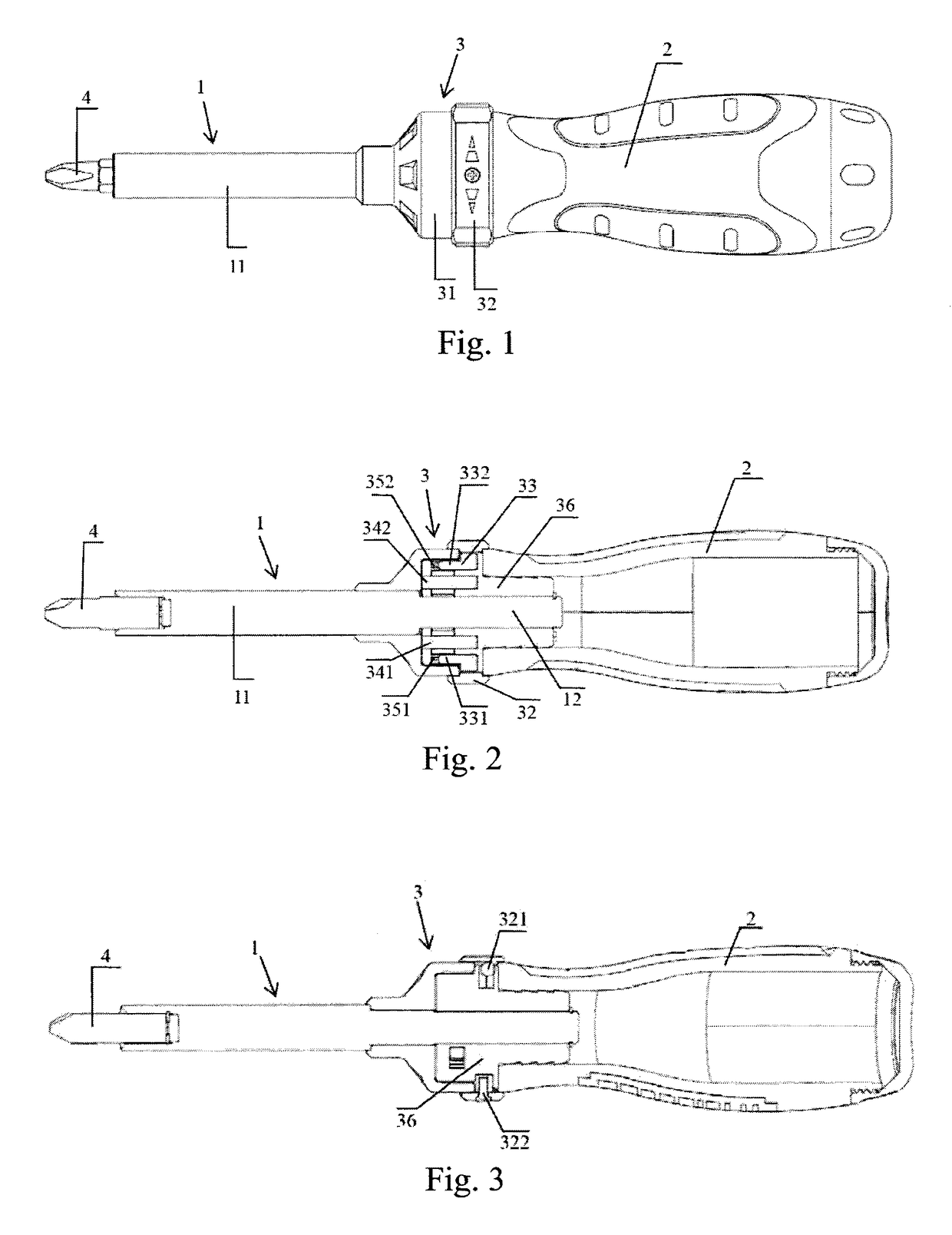
[0049]FIGS. 1-15 show the related structural schematic view of a preferred embodiment of the present invention.

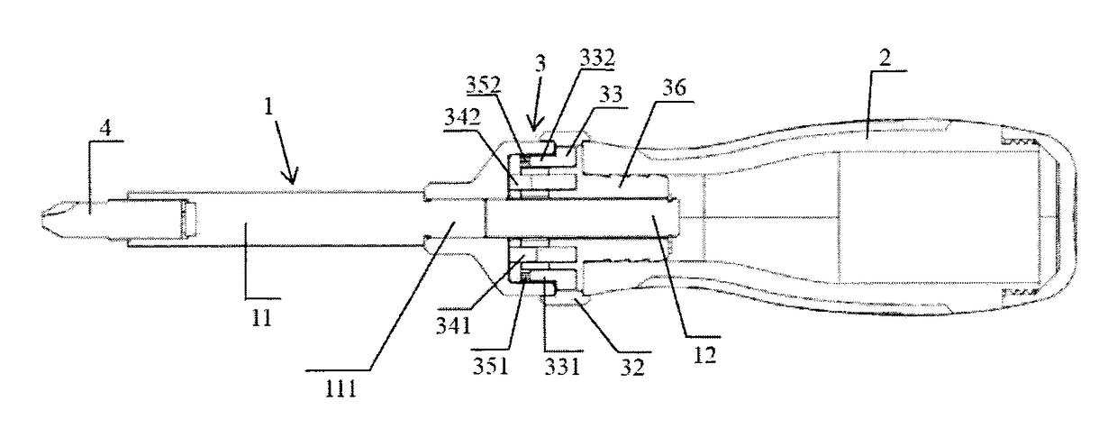
[0050]As shown in FIGS. 1-3, the ratchet tool of the present invention includes a shaft member 1, a handle 2 and a ratchet mechanism 3. The handle 2 is connected to the ratchet mechanism 3, and the shaft member 1 extends into the interior of the ratchet mechanism 3 along the central axle of the ratchet mechanism 3 from the front end of the ratchet mechanism 3 and is connected to the ratchet mechanism 3. In this embodiment, the shaft member 1 preferably passes through the rear end of the ratchet mechanism 3 along the central axle of the ratchet mechanism 3 from the front end of the ratchet mechanism 3 and is connected to the ratchet mechanism 3.

[0051]In which, the shaft member 1 further includes a shaft 11 and an extension portion 12. In this embodiment, the shaft 11 is designed to be integrated with the extension portion 12 which extends into the interior of the ratchet mec...

embodiment two

[0064]This embodiment is similar to Embodiment One, the main difference of which is the structure of the shaft member.

[0065]In this embodiment, the shaft member has a first end away from the handle and a second end adjacent the handle, and a middle portion located between the first end and the second end. The radius of the middle portion is greater than that of the portion extending to both sides from the middle portion. When the first end of the shaft member extends into the interior of the ratchet mechanism, the pawl sleeve is put on, and as the radius of the middle portion is greater, so that axially securing of the shaft member can be realized. Alternatively, when the shaft member is pull out, the second end of the shaft member is inserted into the interior of the ratchet mechanism, the pawl sleeve is put on, and axially securing of the shaft member can also be realized.

[0066]In which, the first end of the shaft member may specifically be an operating portion, such as a sleeve, ...

embodiment three

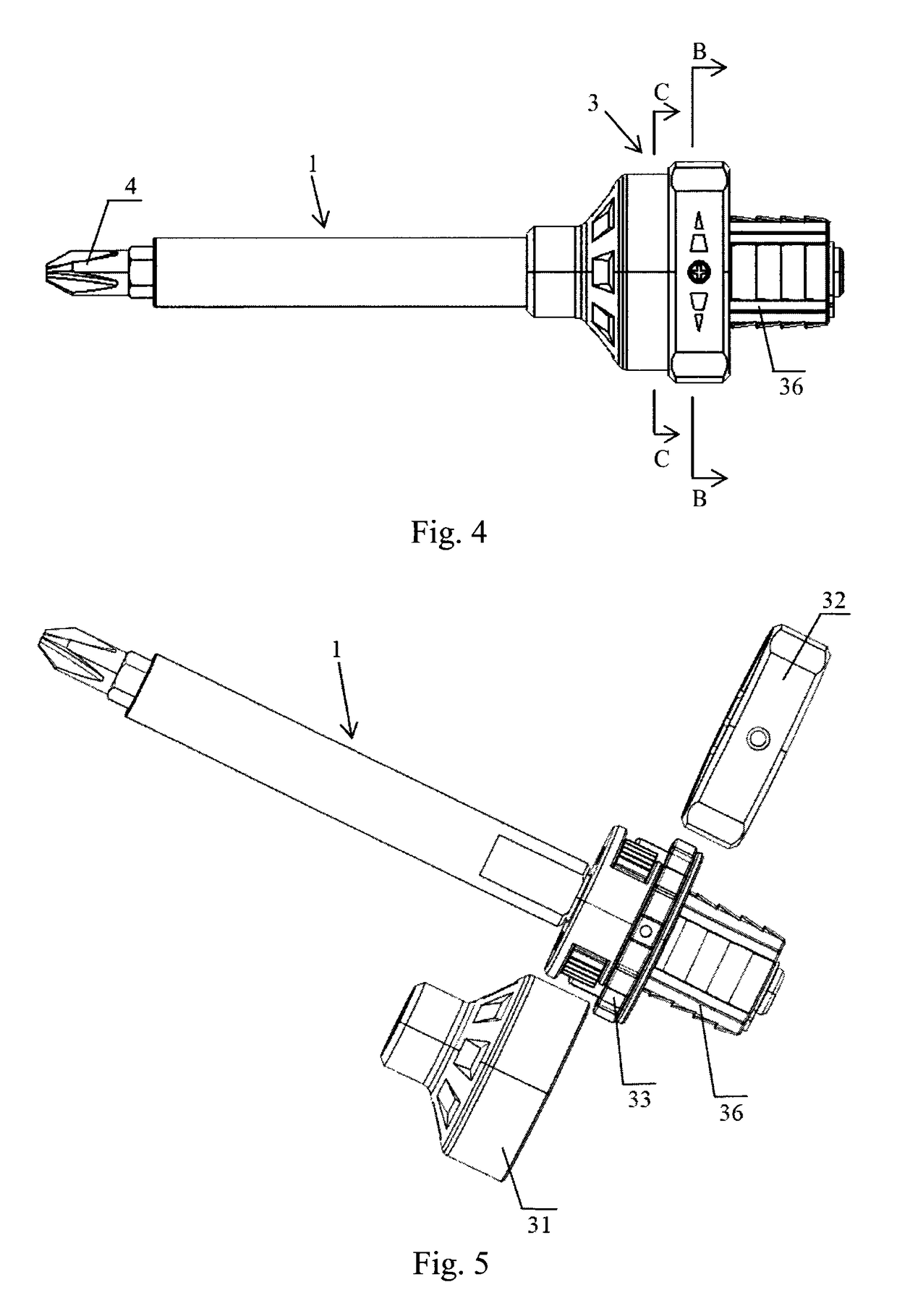
[0067]FIG. 1, FIG. 4 and FIGS. 10-21 illustrate the structural schematic views of another preferred embodiment of the present invention.

[0068]This embodiment is similar to Embodiment One, the main difference of which is the structure of the shaft member 1.

[0069]As shown in FIG. 16, the ratchet tool of the present invention includes a shaft member 1, a handle 2 and a ratchet mechanism 3. The handle 2 is connected to the ratchet mechanism 3, and the shaft member 1 extends into the interior of the ratchet mechanism 3 along the central axle of the ratchet mechanism 3 from the front end of the ratchet mechanism 3 and is connected to the ratchet mechanism 3. In this embodiment, the shaft member 1 preferably passes through the rear end of the ratchet mechanism 3 along the central axle of the ratchet mechanism 3 from the front end of the ratchet mechanism 3 and is connected to the ratchet mechanism 3.

[0070]In which, the shaft member 1 further includes a shaft 11 and an extension portion 12....


PUM


Abstract

A ratchet tool includes a shaft member, a handle and a ratchet mechanism, in which the handle is connected to the ratchet mechanism, and the shaft member extends into the interior of the ratchet mechanism along the central axle of the ratchet mechanism from the front end of the ratchet mechanism and is connected to the ratchet mechanism. The shaft member includes a shaft and an extension portion which passes through the rear end of the ratchet mechanism along the central axle of the ratchet mechanism from the front end of the ratchet mechanism and is connected to the ratchet mechanism, and the shaft is designed to be integrated with or separated from the extension portion. Such a design of the shaft member solves the wobble problem of the shaft. The ratchet tool of the present invention also includes a lighting device. The ratchet tool of the present invention requires small turning force when turning back and has strong capacity of torque transferring, and at the same time achieves lighting feature.

Description

FIELD OF THE INVENTION[0001]The present invention relates to a hand tool and, more particularly, to a ratchet tool.DESCRIPTION OF THE PRIOR ART[0002]Screwdrivers are tools used for screwing a screw to keep it in place, which includes a shaft and a handle. A prior art screwdriver commonly has its shaft secured to the handle. When in use, the hand holding the handle can only turn by a small angle. Therefore, the hand needs to stop several times during the process when an element is required to be rotated consecutively for multiple times, to allow the hand to turn reversely by an angle. One of the methods is to release the screwdriver by the hand holding it temporarily from the element to allow the hand to turn in reverse direction, which requires directing the screwdriver to the element again. Another method is to use the other hand to help and allow the hand holding the handle to release from the handle and turn in reverse direction. Obviously, both methods have inconveniences, which...

Claims


Application Information

Patent Timeline
Patent Type & Authority Patents(United States)
IPC IPC(8): B25B15/04B25B23/18
CPCB25B15/04B25B23/18
Inventor WANG, WEIYI
Owner HANGZHOU GREAT STAR TOOLS
Learn More