
Directional antenna module

a technology of directional antenna modules and antenna supports, which is applied in the direction of antenna supports/mountings, non-resonant long antennas, antennas, etc., can solve the problems of user not having access to this information, excessive weak received signals, and operating errors in the above-mentioned directional antenna modules. achieve the effect of robustness against environmental influences

Active Publication Date: 2017-09-19
ROHDE & SCHWARZ GMBH & CO KG
View PDF11 Cites 0 Cited by
  • Summary
  • Abstract
  • Description
  • Claims
  • Application Information

AI Technical Summary

Benefits of technology

The directional antenna module according to the invention allows for continuous usage of different frequency ranges without the need for manual switching. It is constructed in a way that is particularly robust against environmental influences and does not require a different directional antenna module for coverage of a wide frequency range.

Problems solved by technology

Operating errors can occur in the aforementioned directional antennae modules.
Thus, one possible source of error during measurement is that the user either does not have access to this information during the measurement process or is not even aware that it is necessary to switch between different directional antennae at a particular boundary frequency.
If the user neglects to switch to the other directional antenna, it may therefore occur, in particular for relatively weak received signals, that the measurement using the directional antenna module leads to an excessively weak received signal and the measurement or location thus fails.

Method used


Image

  • Directional antenna module
  • Directional antenna module
  • Directional antenna module

Examples


Embodiment Construction

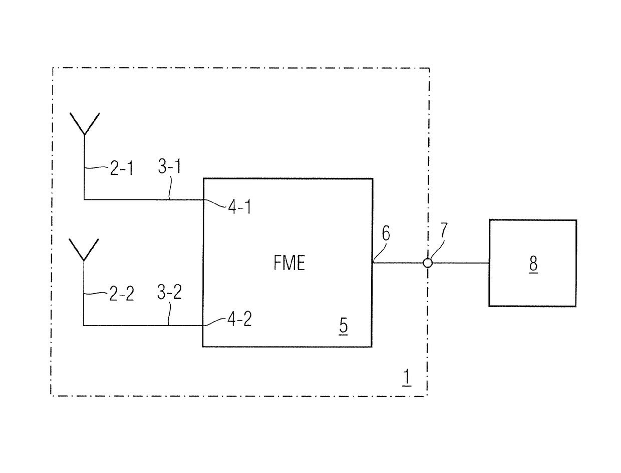
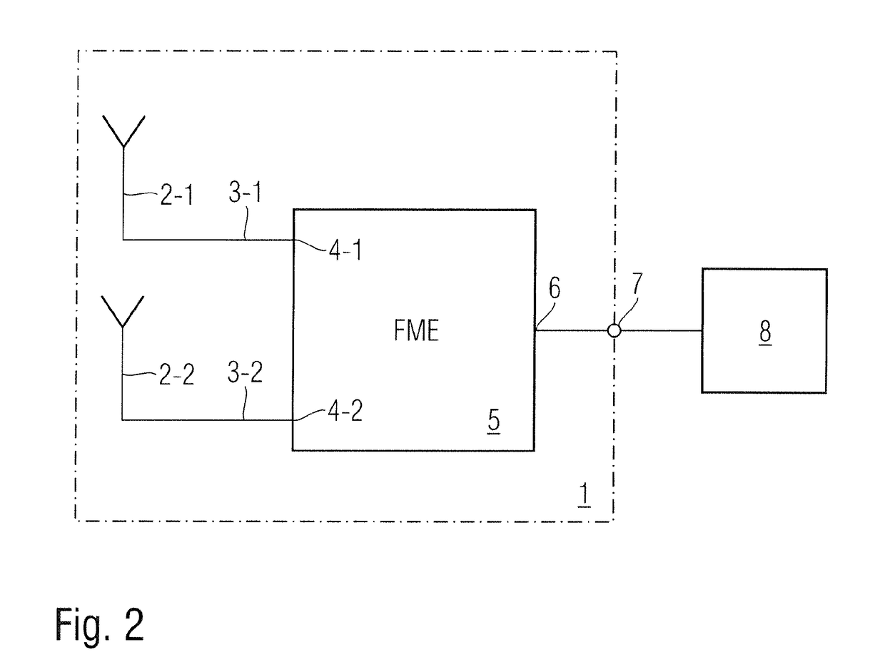
[0033]As can be seen from FIG. 2, in the embodiment shown, the directional antenna module 1 according to the invention comprises two directional antennae 2-1, 2-2, contained in a housing of the directional antenna module 1, for adjacent frequency ranges. The two directional antenna modules 2-1, 2-2 are connected via antenna signal lines 3-1, 3-2 to input gates 4-1, 4-2 of a passive frequency multiplexing unit 5, which multiplexes the antenna signals received from the two directional antennae 2-1, 2-2 in the various frequency ranges into a wideband signal and emits them via an output gate 6 and a directional antenna module terminal 7 to a signal evaluation unit 8. The signal evaluation unit 8 may be a signal receiver or for example a spectrum analyser. The signal evaluation unit 8 is connectable to the directional antenna module 1. In a possible embodiment, the directional antenna module 1 is attached to a handle which is connected to the signal evaluation unit 8. The two directional...


PUM


Abstract

Directional antenna module (1) comprising at least two directional antennae (2-1, 2-2), contained in a housing (12) of the directional antenna module (1), for adjacent frequency ranges, wherein the directional antennae (2-1, 2-2) are connected to a passive frequency multiplexing unit (5), which multiplexes the antenna signals received from the directional antennae in the various frequency ranges into a wideband signal.

Description

PRIORITY CLAIM[0001]This application claims the benefit of European Patent Application No. 15179508.5, filed Aug. 3, 2015; the disclosure of which is incorporated herein by reference in its entirety.TECHNICAL FIELD[0002]The invention relates to a directional antenna module which supplies a wideband signal for a receiver or spectrum analyser connected thereto.TECHNICAL BACKGROUND[0003]A directional antenna is an antenna which, as a receiving antenna, has a maximum sensitivity in a particular direction. As receiving antennae, directional antennae have a non-isotropic or anisotropic directional characteristic, in other words they have a directional effect. This directional effect can be described quantitatively by the directional factor. The directional characteristic of an antenna can be specified more precisely in an antenna diagram or directional diagram. Similarly to microphones, antennae have different antenna characteristics, for example omnidirectional, cardioid or bidirectional...

Claims


Application Information

Patent Timeline
Patent Type & Authority Patents(United States)
IPC IPC(8): H01Q1/24H01P1/213H01Q1/42H01Q7/00H01Q11/10H01Q21/30H01Q5/50H01Q21/06H01Q1/27
CPCH01Q1/243H01P1/213H01Q1/42H01Q5/50H01Q7/00H01Q11/10H01Q21/062H01Q21/30H01Q1/273H01Q5/20H01Q1/50H01Q23/00
Inventor NEINHUES, MARKUS
Owner ROHDE & SCHWARZ GMBH & CO KG
Learn More