
Near-threshold optical transmitter pre-distortion

a transmitter and optical technology, applied in the field of optical communication, can solve the problems of large electrical power consumption of circuits, difficult to realize optical devices (lasers and detectors), and difficult to realize amplifier circuits that have sufficient raw bandwidth with acceptable power consumption, and achieve the effect of quickly bringing the emitter into a linear operating rang

Active Publication Date: 2017-08-15
IBM CORP
View PDF19 Cites 7 Cited by
  • Summary
  • Abstract
  • Description
  • Claims
  • Application Information

AI Technical Summary

Benefits of technology

This patent describes a transmitter that has a special feature called a "pre-distortion equalization controller" which helps to quickly and accurately control the output of the transmitter. This feature is important because it helps to keep the transmitter running at its best possible level of efficiency, which can save a lot of power and reduce interference. Overall, this patent shows how to create a more precise and efficient transmitter that can produce better quality signals.

Problems solved by technology

The biggest challenge for short-reach interconnects is to produce active components, namely optical transmitters and receivers, that provide sufficient bandwidth to operate at high data rates (e.g., >25 Gb / s) while maintaining low power consumption to maximize the power efficiency (commonly expressed in mW / Gb / s or pJ / bit: the energy required to transmit a bit of information).
However, as data rates have increased beyond 10 Gb / s, it is difficult to realize optical devices (lasers and detectors) and amplifier circuits that have sufficient raw bandwidth with acceptable power consumption.
To achieve the highest data rates, the lasers are operated at high current densities and the circuits typically consume large amounts of electrical power to deliver high speed performance.

Method used


Image

  • Near-threshold optical transmitter pre-distortion
  • Near-threshold optical transmitter pre-distortion
  • Near-threshold optical transmitter pre-distortion

Examples


Embodiment Construction

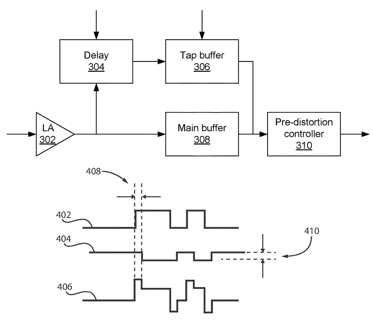
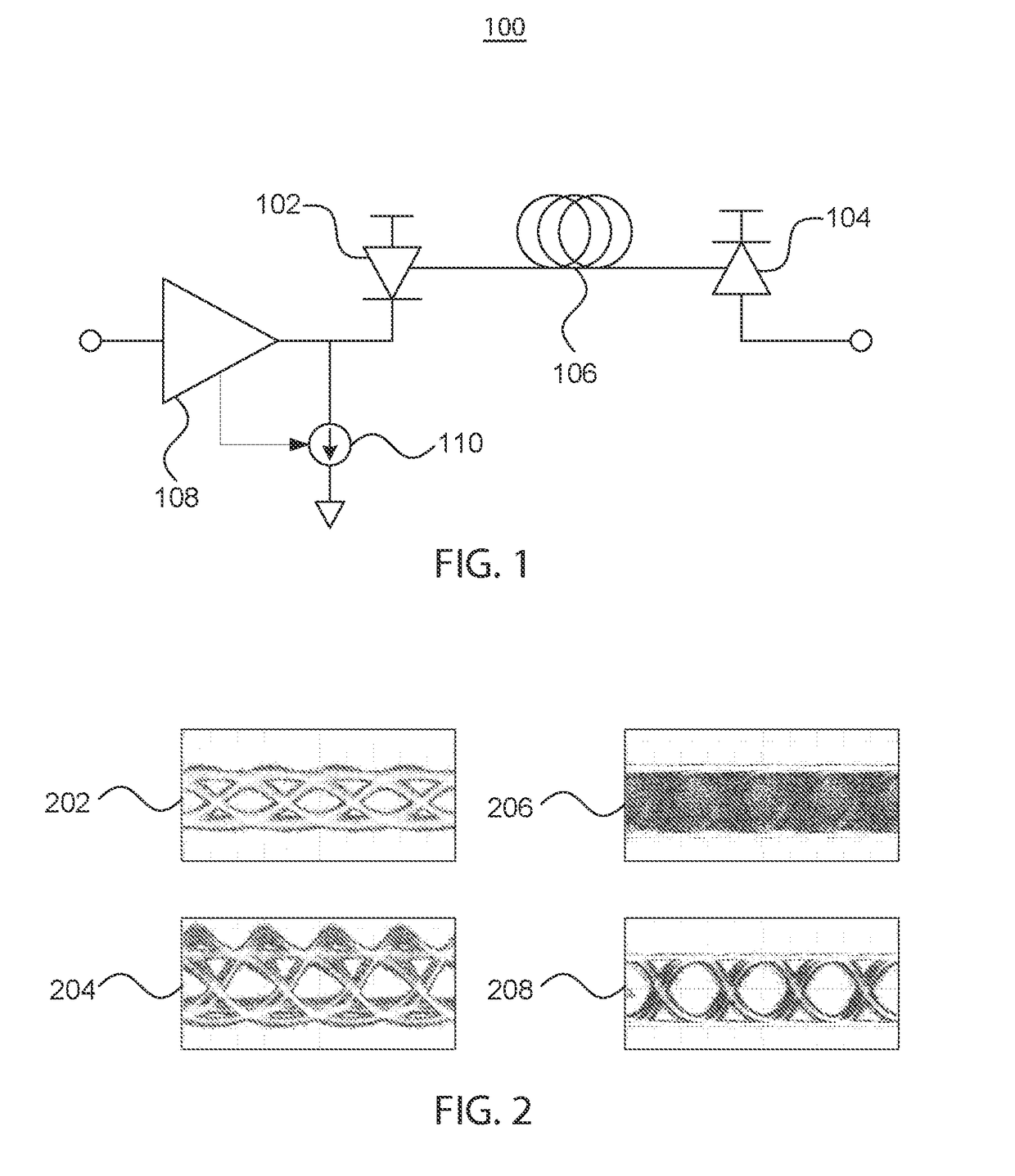
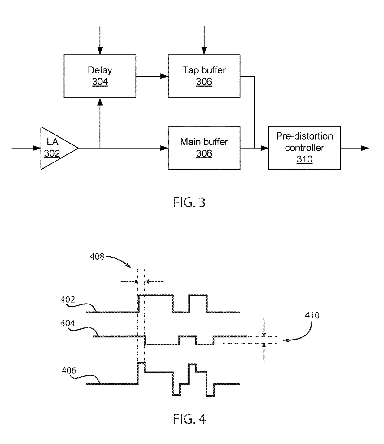
[0021]Embodiments of the present invention lower the power dissipation of emitters, such as vertical-cavity surface-emitting lasers (VCSELs), that run optical links by biasing the VCSEL close to (or below) the emitter's threshold current. This allows the VCSEL to be used with a lower power consumption, but results in turn-on jitter. The present embodiments therefore employ pre-distortion (otherwise known as pre-emphasis and feed-forward) transmitter equalization to compensate for the resulting inter-symbol interference and turn-on delay distortion. The pre-distortion is optimized for the entire end-to-end link, rather than simply optimizing the waveform of the VCSEL output signal. Although the present embodiments are set forth with a specific focus on VCSELs, it should be understood that the present principles may be applied to any optical link based on semiconductor lasers, e.g., edge emitting semiconductor lasers.

[0022]The present principles apply equalization to overcome the limi...


PUM


Abstract

Methods an systems for low-power transmission include biasing an emitter in a non-linear operating range of the emitter near a threshold current of the emitter. A data signal is distorted to add a precursor pulse to a rising edge of a data waveform to quickly bring the emitter into a linear operating range. The distorted data signal is transmitted at the emitter.

Description

BACKGROUND[0001]Technical Field[0002]The present invention relates to optical communications and, more particularly, to transmitter pre-distortion in optical transmitters using semiconductor lasers.[0003]Description of the Related Art[0004]Short-reach interconnects using multi-mode optical fiber (MMF), over distances on the order of 100 m, are widely used in computer systems, data centers, and campus networks. For these data links, the optical channel contributes relatively little signal degradation for 10-40 Gb / s data rates. In addition, generations of fiber with optimized modal bandwidth continue to be developed that minimize the optical channel as the primary source of signal degradation. The biggest challenge for short-reach interconnects is to produce active components, namely optical transmitters and receivers, that provide sufficient bandwidth to operate at high data rates (e.g., >25 Gb / s) while maintaining low power consumption to maximize the power efficiency (commonly e...

Claims


Application Information

Patent Timeline
Patent Type & Authority Patents(United States)
IPC IPC(8): H04B10/2507H04B10/58H04B10/508H04B10/50
CPCH04B10/508H04B10/2507H04B10/504H04B10/58H04B10/50572
Inventor DOANY, FUAD E.KUCHTA, DANIEL M.PROESEL, JONATHAN E.RYLYAKOV, ALEXANDER V.SCHOW, CLINT L.TAUBENBLATT, MARC A.
Owner IBM CORP
Learn More