Method for manufacturing gas turbine blade, and gas turbine blade

a technology of gas turbine blades and manufacturing methods, which is applied in the direction of machines/engines, solid-state diffusion coatings, mechanical devices, etc., can solve the problems of increased temperature of the wastage of the cooling pass by oxidation, and exposed inner surface of the cooling pass, so as to improve oxidation resistance, improve toughness and ductility, and the blade fatigue strength is very important

Active Publication Date: 2017-08-15
MITSUBISHI POWER LTD
View PDF22 Cites 0 Cited by
  • Summary
  • Abstract
  • Description
  • Claims
  • Application Information

AI Technical Summary

Benefits of technology

[0014]When Al2O3 is produced as the internal oxide, the oxidation of Ni, Cr, and any other alloying-element that is contained in the substrate of the blade unfavorably advances, so that advantageous effects based on the Al coating are not produced. On the contrary, the oxidization may be accelerated.
[0015]In a gas turbine blade, centrifugal force, thermal stress based in a difference in temperature between combustion gas and cooling air, and other stresses are generated. These stresses are complicatedly changed by starting or stopping the action of the gas turbine. Thus, the fatigue strength of the blade is very important. In connection with the fatigue strength, a high-Al-concentration alloy layer formed by Al coating, such as NiAl, is poor in toughness and ductility to decline the blade in strength reliability, in particular, fatigue strength.
[0016]The degree of this decline in the fatigue strength depends on the material of the blade. However, the degree is remarkably increased at low temperatures of about 600° C. or lower.
[0017]Apart from the above, the temperature distribution of the inner surface of the cooling pass of the gas turbine blade is uneven and depends on the design of the blade. However, almost all of temperatures of the blade are designed to be about 700° C. Edges of the blade, or the leading edge and the trailing edge of the blade, and other high-temperature regions thereof are designed to be adjusted to about 900° C.
[0018]Accordingly, when Al coating is applied onto a low-temperature portion of the inside of the cooling pass, the region is improved in oxidation resistance. However, the degree of the improvement is small. About the fatigue strength, the application of the Al coating makes the strength low to decline the reliability of the gas turbine blade.
[0019]However, in conventional Al coating techniques using CVD, Al is supplied through a gas fluid containing Al, and the Al-supply aims for the application of coating onto the whole of the inner surface of a cooling pass. Thus, Al coating is unfavorably applied also to a region, inside the cooling pass inner surface, turned into a temperature range where a bad effect is produced on the reliability of the blade by the Al coating.

Problems solved by technology

However, even when gas turbines are cooled, a rise in the temperature of the inner surface of their cooling pass is unavoidable with the advance of the tendency of heightening the temperature of the gas turbines.
In particular, the inner surface of the cooling pass, which is exposed to high temperature, is deteriorated by oxidation, so that the following two problems are caused:
The first problem of the two is the wastage of the pass by the oxidation.
However, the inner surface of the cooling pass is oxidized so that the surface of the bulges and depressions undergo wastage.
The second problem is the blockage of the cooling pass by oxides peeled from the inner surface.
Specifically, the cooling pass is generally narrow and meandering to be complicatedly configured, so that oxides peeled therefrom deposit easily onto a cooling-air flow-rate change zone of the cooling pass.
As described above, the cooling pass is complicatedly configured inside the blade, and is further narrow; thus, it is difficult to apply, to the pass, thermal spraying, electron beam physical vapor deposition (EB-PVD), overlay coating based on electroplating, or any other method that is generally used to give oxidation resistance to the outer surface of a blade.
However, at temperatures of about 700° C., Al2O3 is thermodynamically unstable.
These stresses are complicatedly changed by starting or stopping the action of the gas turbine.
In connection with the fatigue strength, a high-Al-concentration alloy layer formed by Al coating, such as NiAl, is poor in toughness and ductility to decline the blade in strength reliability, in particular, fatigue strength.
Apart from the above, the temperature distribution of the inner surface of the cooling pass of the gas turbine blade is uneven and depends on the design of the blade.
However, the degree of the improvement is small.
About the fatigue strength, the application of the Al coating makes the strength low to decline the reliability of the gas turbine blade.
Thus, Al coating is unfavorably applied also to a region, inside the cooling pass inner surface, turned into a temperature range where a bad effect is produced on the reliability of the blade by the Al coating.
However, about the inner surface of a cooling pass of the blade, which is narrow and is complicatedly configured, it is very difficult to apply a proper masking thereto highly precisely.
Furthermore, the removal of the applied mask is likewise difficult.
Furthermore, Patent Document 1 does not naturally disclose a technique of setting an Al coating portion in accordance with the temperature distribution of the inner surface of the cooling pass.
Accordingly, even when the technique disclosed in Patent Document 1 is used, it is never possible to attain both of an improvement in the oxidation resistance and a restraining of a decline in the fatigue strength.

Method used


Image

  • Method for manufacturing gas turbine blade, and gas turbine blade
  • Method for manufacturing gas turbine blade, and gas turbine blade
  • Method for manufacturing gas turbine blade, and gas turbine blade

Examples


examples

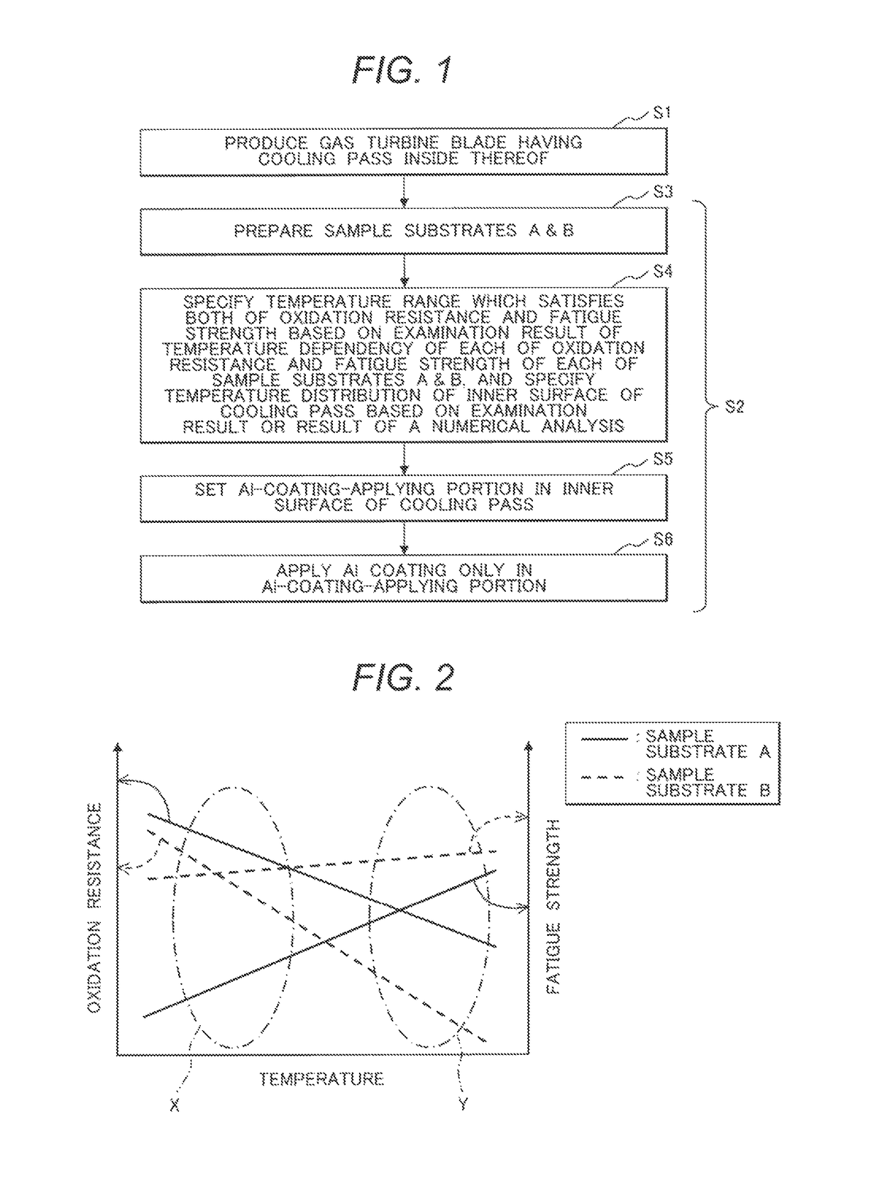
[0090]The following will demonstrate specific examples of the Al coating method of the present invention.

[0091]An Ni-based alloy (Ni-13.8Cr-6.8Co-1.8Mo-4.0W-4.0Al-2.8Ta-1.2Nb-3.4Ti-0.015B-0.14C (mass %)) suitable for gas turbine members was precisely casted and then the resultant was subjected to machine work to yield a gas turbine blade having at the inside thereof a cooling pass.

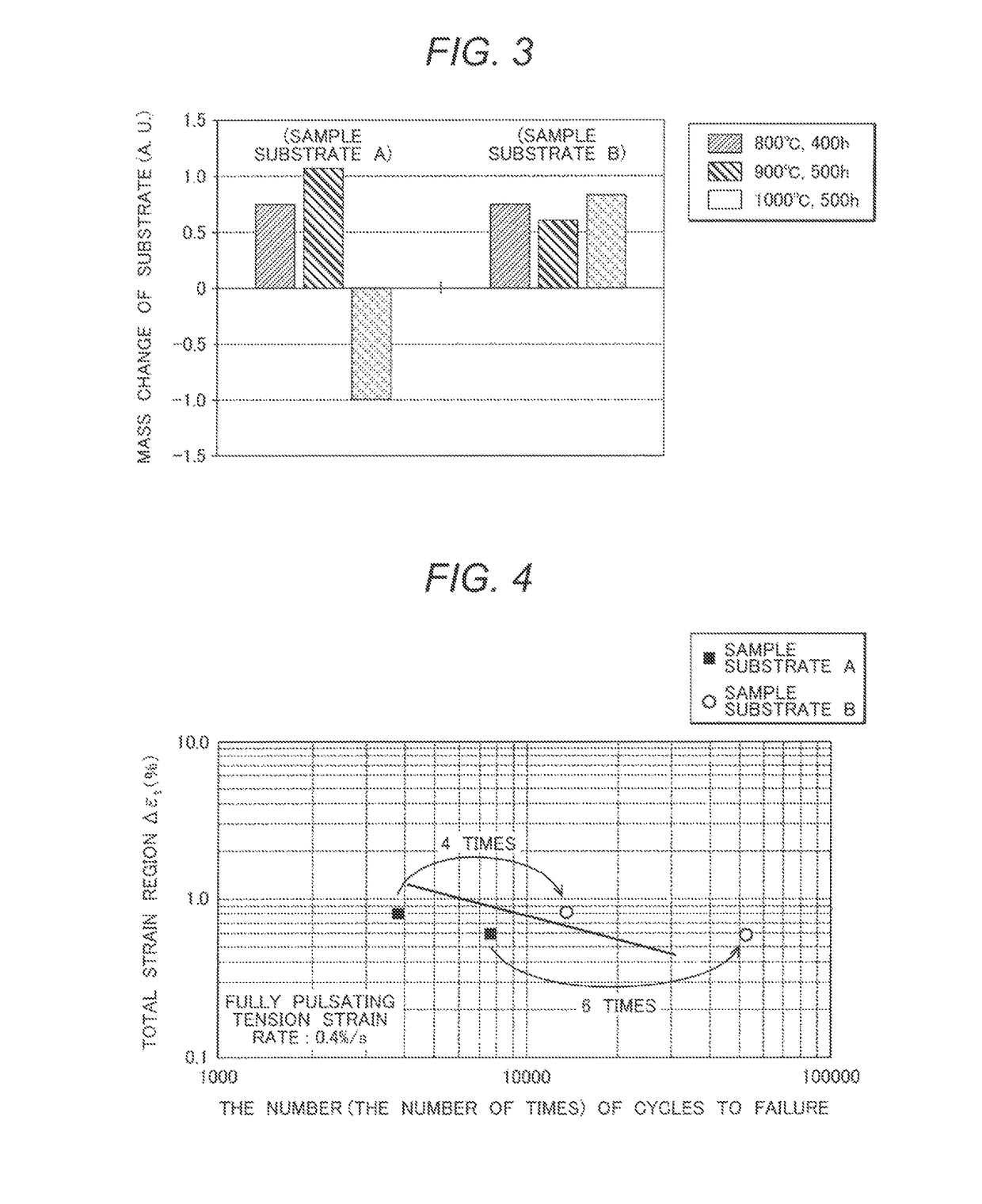
[0092]About this gas turbine blade, on the basis of the shape of the internal cooling pass, the volume of cooling air, and others, a temperature distribution in the inner surface of the cooling pass was gained by a numerical analysis. The present example gave a result that the respective temperatures of the leading edge and the trailing edge of the blade tip reached to a high temperature of 900° C. and the temperatures of most portions of the blade were 800° C. or lower.

[0093]In order to examine the temperature dependencies of the oxidation resistance and the fatigue strength of the blade, a high temperatu...


PUM

PropertyMeasurementUnit
temperaturesaaaaaaaaaa
temperatureaaaaaaaaaa

Abstract

This method is a method for manufacturing a gas turbine blade, including:producing a gas turbine blade having a cooling pass inside thereof; andpartially coating an inner surface of the cooling pass with Al.The step of partially coating an inner surface of the cooling pass with Al further including:a first step of specifying a temperature range which satisfies both of oxidation resistance and fatigue strength and the temperature distribution of the inner surface of the cooling pass based on an examination result or result of a numerical analysis;a second step of setting an Al-coating-applying portion of the inner surface of the cooling pass as the temperature range specified at the first step; anda third step of applying Al coating only into the set Al-coating-applying portion.

Description

CLAIM OF PRIORITY[0001]The present application claims priority from Japanese Patent application serial No. 2013-112755, filed on May 29, 2013, the content of which is hereby incorporated by reference into this application.BACKGROUND OF THE INVENTION[0002]1. Field of the Invention[0003]The present invention relates to a method for manufacturing a gas turbine blade having at the inside thereof a cooling pass, in which Al coating is applied onto the partial area of an inner surface of the cooling pass; and a gas turbine blade in which Al coating is applied onto a partial area of the inner surface of a cooling pass by this method.[0004]2. Description of the Related Art[0005]In recent gas turbines, a tendency of heightening the temperature of combustion gas therein has been advancing to aim for a rise in the efficiency of the turbines. The combustion gas temperature has already exceeded the melting point of a heat resistant alloy used in their turbine blade, turbine nozzle, and other com...

Claims


Application Information

Patent Timeline
Patent Type & Authority Patents(United States)
IPC IPC(8): B23P15/02F01D5/28C23C10/48F01D5/18B22D21/02C23C10/04C23C10/60
CPCC23C10/04B22D21/025B23P15/02C23C10/48C23C10/60F01D5/18F01D5/187F01D5/288F05D2230/211Y10T29/49337Y10T29/49341
Inventor IZUMI, TAKESHIARIKAWA, HIDEYUKIKOJIMA, YOSHITAKAMEBATA, AKIRAKASUYA, TADASHIIMANO, SHINYAMIYAMOTO, KOJI
Owner MITSUBISHI POWER LTD
Why Eureka
Try Eureka