
Adjustable testing apparatus for an orthopaedic specimen such as a knee implant prosthesis

a technology for orthopaedic specimens and testing equipment, which is applied in the field of orthopaedic specimen testing equipment, can solve the problems of low accuracy of electrohydraulic actuators, so as to eliminate the use of electrohydraulic actuators, improve accuracy, and improve accuracy

Active Publication Date: 2017-08-15
ORTHOPAEDIC RES LAB
View PDF2 Cites 0 Cited by
  • Summary
  • Abstract
  • Description
  • Claims
  • Application Information

AI Technical Summary

Benefits of technology

[0027]A primary advantage of the disclosure relates to eliminating use of electrohydraulic actuators (and associated controls and sensors) in the testing apparatus.
[0028]Another benefit of the disclosure is the preparation of a testing apparatus that is dependable, durable, and accurate.
[0029]Still another advantage relates to the ability to easily replicate multiple testing apparatus into a multiple station system.
[0030]Yet another benefit resides in the reduced cost to manufacture a reliable system.

Problems solved by technology

Unfortunately, these electrohydraulic actuators are relatively expensive.
Further, the electrohydraulic actuators are not particularly effective in measuring smaller forces (e.g. on the order of less than 70 N) nor do the electrohydraulic actuators have good resolution.
Also, use of the electrohydraulic actuators and associated controls require expensive sensors in an effort to achieve coordinated synchronization or phased movement as required under the ISO standard.
As a result, the use of multiple electrohydraulic actuators, and the associated sensors and controls for the actuators, results in a test apparatus that is unduly expensive.
These problems are magnified when the test apparatus is designed to simultaneously test multiple test specimens.

Method used


Image

  • Adjustable testing apparatus for an orthopaedic specimen such as a knee implant prosthesis
  • Adjustable testing apparatus for an orthopaedic specimen such as a knee implant prosthesis
  • Adjustable testing apparatus for an orthopaedic specimen such as a knee implant prosthesis

Examples


Embodiment Construction

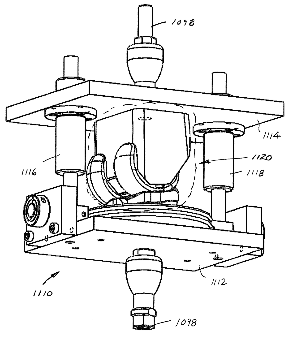
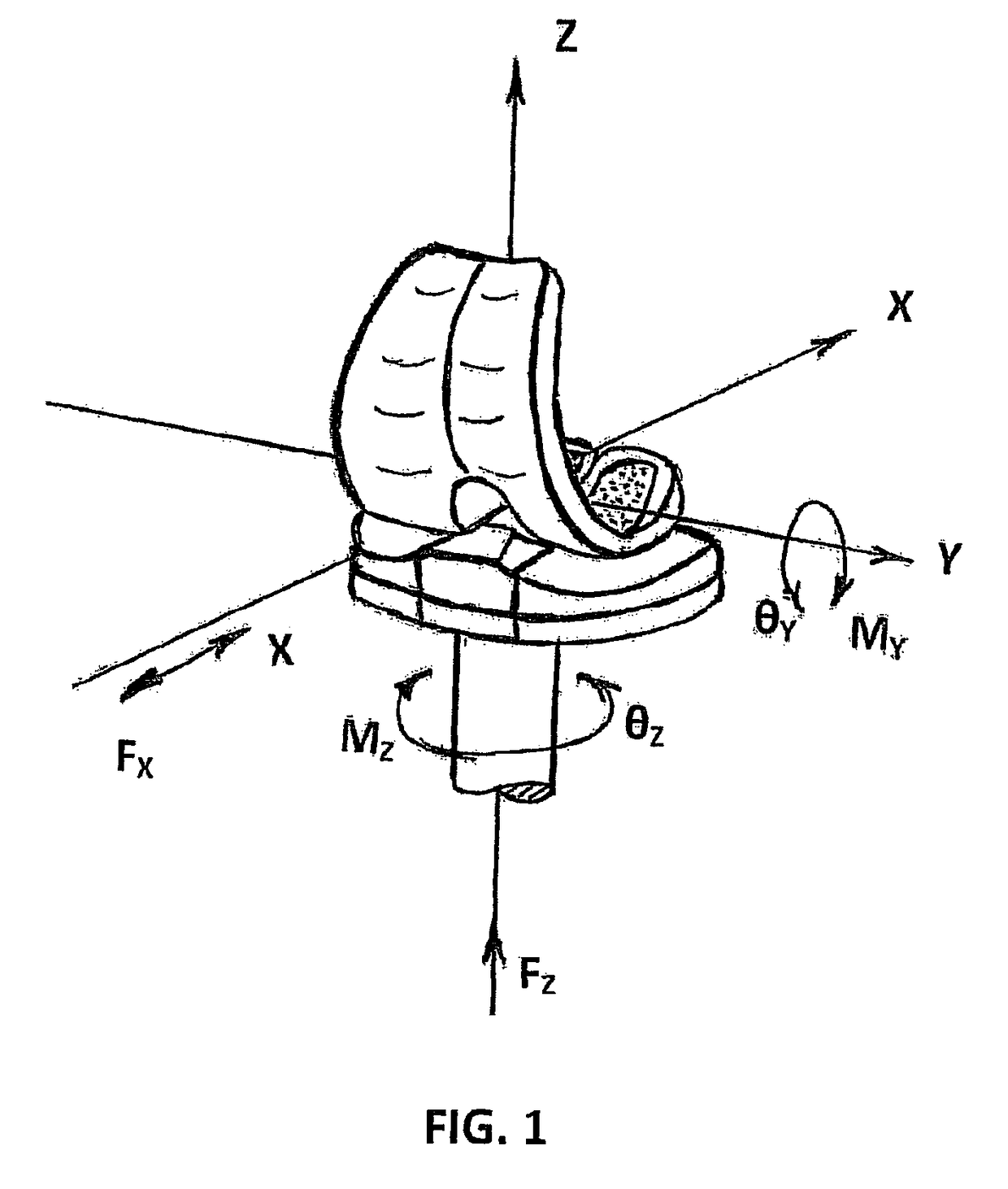
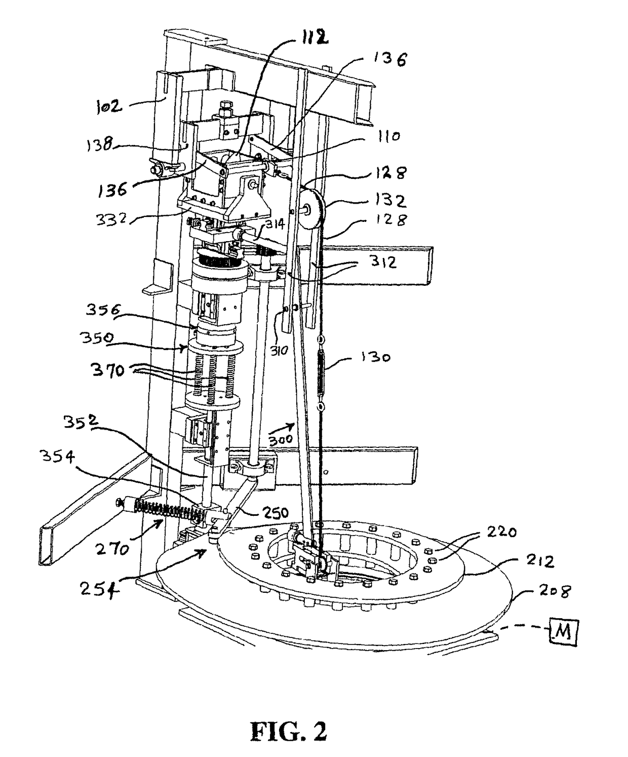
[0051]The machine described herein produces three kinematic motions and a dynamic force along the three axes of an orthogonal coordinate system which is fixed in space with its origin located within the specimen. FIG. 1 depicts the set of orthogonal system axes with the kinematic motions and dynamic force schematically shown. For example, the first kinematic motion [ey] is rotation about the first axis of the orthogonal coordinates which is produced by the moment My. The second kinematic motion [ez] is rotation about the second axis produced by the moment Mz. The dynamic force Fz acts along the same axis. The third kinematic motion is linear translation [X] which takes place along the third axis in response to the force Fx. FIG. 2 shows a testing apparatus 100 supported by a frame 102 that includes a test chamber 110 for receiving an associated test specimen 112. The test chamber 110 is preferably configured so that the lower portion of test specimen 112 when mounted therein does no...


PUM


Abstract

A testing apparatus for exposing an associated specimen(s) to motions along multiple axes is provided. The testing apparatus includes a test chamber and first, second, third, and fourth devices that impose different kinematic motions or forces on the specimen. A drive mechanism is connected to the first, second, third, and fourth devices so that motion from a single axis is conveyed by the first, second, third and fourth devices to deliver the desired kinematic motions and / or forces to the test chamber(s). At least one of the first, second, third, and fourth devices includes an adjustment mechanism to modify at least one of the devices.

Description

[0001]This continuation-in-part application claims the priority benefit of co-pending U.S. application Ser. No. 13 / 841,645, filed Mar. 15, 2013, the disclosure of which is expressly incorporated herein in its entirety.BACKGROUND OF THE DISCLOSURE[0002]This disclosure relates to a testing apparatus for orthopaedic specimens. In particular, this disclosure relates to a testing apparatus that is used to apply motions and forces to a test specimen(s) in a manner representative of what a prosthesis may encounter when implanted.[0003]Various suppliers design and manufacture orthopaedic specimens in an effort to evaluate the suitability of a particular design for use such as a prosthesis, for example, a knee implant. Before these new designs are available for use, specimens must undergo rigorous testing under prescribed conditions. For example, ISO 14243 is a standard that sets forth criteria for evaluating the design and materials of knee implants, and particularly aids in evaluating the ...

Claims


Application Information

Patent Timeline
Patent Type & Authority Patents(United States)
IPC IPC(8): G01B5/30A61F2/76A61F2/46A61F2/38
CPCA61F2/468A61F2/38A61F2/76
Inventor RASHIDI, MAJIDKATZ, ALONPOSTAK, PAUL D.GREENWALD, A. SETH
Owner ORTHOPAEDIC RES LAB
Learn More