
Rotary encoder switch

a rotary encoder switch and encoder technology, applied in the field of switches, can solve the problems of ineffective engagement with the tooth-shaped structure, inability to perform fine performance of applied products, and inability to provide indicators for traditional rotary switches, etc., to achieve the effect of easy recognition, poor performance and decent performance of application products

Active Publication Date: 2017-08-08
CHU CHING HSIUNG
View PDF5 Cites 2 Cited by
  • Summary
  • Abstract
  • Description
  • Claims
  • Application Information

AI Technical Summary

Benefits of technology

[0007]Accordingly, an object of the present invention is to provide a rotary encoder switch having a structure of indicating rotary position of multistage switches and having a simple structure for improving waterproof ability.
[0008]Another object of the present invention is provide a rotary encoder switch being capable of continuously rotating multiple cycles to generate different encoding signals so as to enable a decent performance of an applied.
[0014]The rotary encoder switch of the present invention utilizes the engagement of the resilient element and the interfering tooth portion of the rotary element to position the rotation of the rotary element driven by the cover cap, whereby effectively addressing the problem that a flexible plate of cantilever structure utilized in a traditional switch to position the rotary element tends to be damaged or disengaged after frequent use. Additionally, the maximum power supply to an applied product can be divided into a plurality of segment values by rotation of the cover cap, whereby generating an encoding signal which corresponds to a respective segment value according to each rotary position of the cover cap or the rotary element. Therefore, the rotary encoder switch is capable of reaching each one of the plurality of segment values by continuously rotating several cycles so as to enable a decent performance of an application product, whereby overcoming drawbacks of a traditional switch that is only capable of providing a limited number of switches and a poor performance. Furthermore, the first lighting elements in cooperation with the cover cap allow users to easily recognize where a rotary position is being reached.

Problems solved by technology

However, the metal flexible plate is a sort of cantilever structure which tends to produce material fatigue after use for a period of time and thus resulting in ineffective engagement with the tooth-shaped structure.
However, a traditional mechanical rotary switch is merely allowed to provide a certain number of stages for being switched, inasmuch as the number of stages allowed to be reached is limited within a single rotation of the knob.
Therefore, fine performance of applied products cannot be performed due to limited control of switches.
In addition to the above-mentioned drawbacks, traditional rotary switches are not provided with indicator for indicating where rotary positioning is reached.
Consequently, users cannot recognize which stage is being reached and thus has no reference position on the knob to be relied on for rotating in a desired position, particularly in a dim place.

Method used


Image

  • Rotary encoder switch
  • Rotary encoder switch
  • Rotary encoder switch

Examples


Embodiment Construction

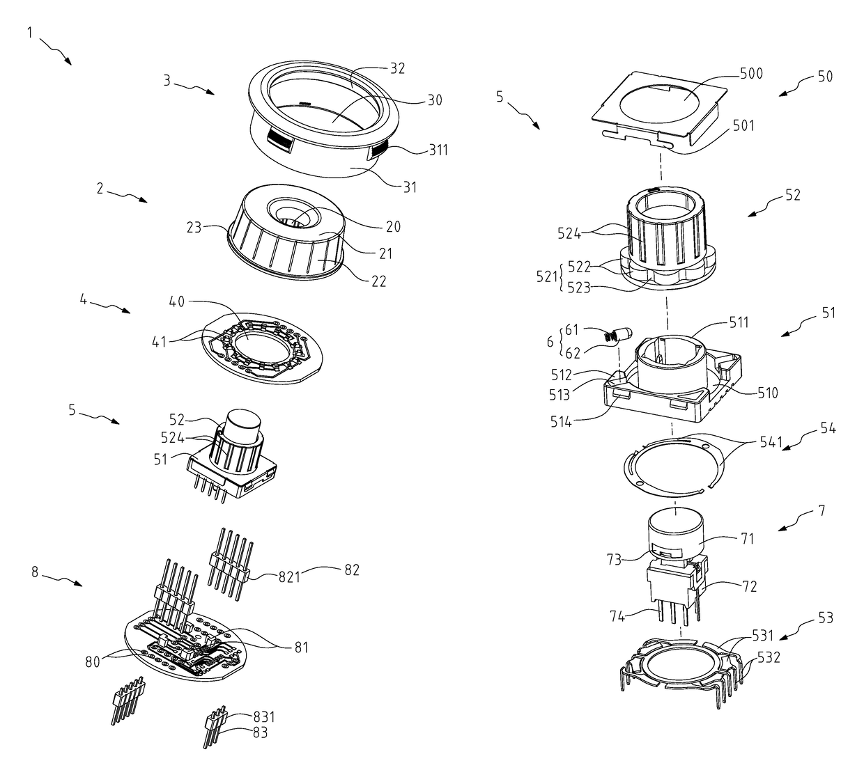
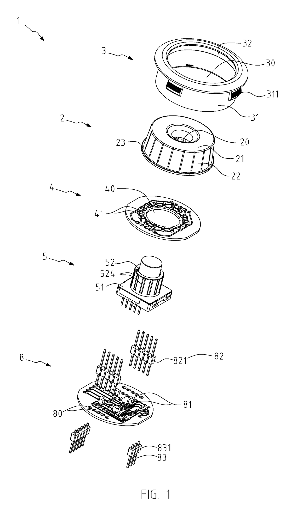
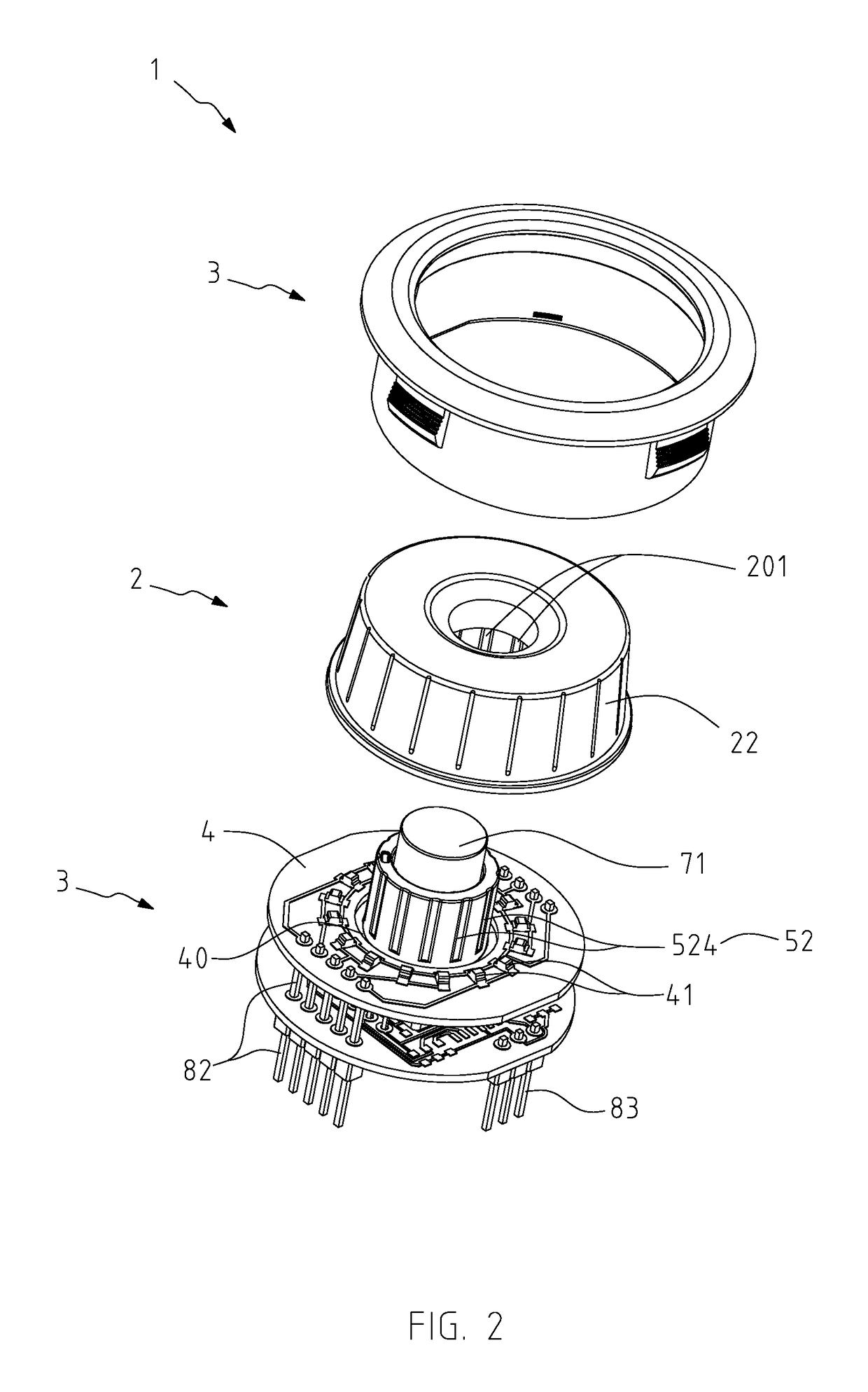
[0024]A rotary encoder switch 1 of the present invention is applicable to electronic products, electric appliances or lighting devices for switching on or switching off or for controlling other functions thereof, such as, adjusting brightness of a light device, volume, wind velocity (e.g. a fan), or fire power (e.g. a gas stove) so as to precisely control an application product by multistage switches.

[0025]Referring to FIGS. 1 to 6 illustrating a preferable embodiment of the present invention, the rotary encoder switch comprises a cover cap 2, a fixing sleeve 3, a first base board 4, an actuating device 5, and a second base board 8. The cover cap 2, made of light permeable material and having a round shape, comprises a display face 21, a covering wall 22 extending downward from peripheral edges of the display face 21, and a sleeve body 20 penetrating the display face 21 and extending downward. The sleeve body 20 of the cover cap 2 comprises multiple engaging ribs 201 protruding from...


PUM


Abstract

A rotary encoder switch includes a cover cap, a fixing sleeve, a first base board, an actuating device, and a second base board disposed under the actuating device. The actuating device includes a base seat and a rotary element rotatably connected to the base seat and mounted to the cover cap. The first base board is disposed on the actuating device and has multiple first lighting elements. The rotary element is rotatable in conjunction with rotation of the cover cap so as to generate encoding signals according to each rotary position of the cover cap for controlling functions of an applied product. The first lighting elements are capable of emitting light in sequence subject to the rotation of the cover cap, while the light being emitted is permeable to the cover cap for users to easily recognize the exact rotary position of the cover cap.

Description

BACKGROUND OF THE INVENTION[0001]1. Field of the Invention[0002]The present invention relates to a switch, and more particularly to a rotary encoder switch having both mechanical and encoding structure and being capable of continuously rotating to provide multistage switches with indications of each stage.[0003]2. Related Art[0004]Generally, electronic products are provided with switches for switching on / off or controlling functions thereof. There are numerous types of switches that are mainly designed to control functions of products being applied to. For instance, controlling rotational speed of a fan, blowing velocity or setting temperature of an air conditioner, brightness of a lamp, or strength of signals of a radio.[0005]A traditional mechanical rotary switch is known to consist of mechanical elements including a main body and a knob pivotally connected to the main body for being rotated, where rotary positioning of the knob is achieved by engagement of a tooth-shaped structur...

Claims


Application Information

Patent Timeline
Patent Type & Authority Patents(United States)
IPC IPC(8): H01H9/00H01H19/02H01H19/11H01H19/06
CPCH01H19/025H01H19/115H01H19/06H01H2221/01H01H2221/07
Inventor CHU, CHING-HSIUNG
Owner CHU CHING HSIUNG
Learn More