
Hernia patch frame incorporating bio-absorbable material

a bio-absorbable material and hernia patch technology, applied in the field of hernia patch repair, can solve the problem that the prosthesis was somewhat difficult to deliver through a trocar of a sufficiently small diameter

Active Publication Date: 2017-07-04
BROWN RODERICK B
View PDF5 Cites 0 Cited by
  • Summary
  • Abstract
  • Description
  • Claims
  • Application Information

AI Technical Summary

Benefits of technology

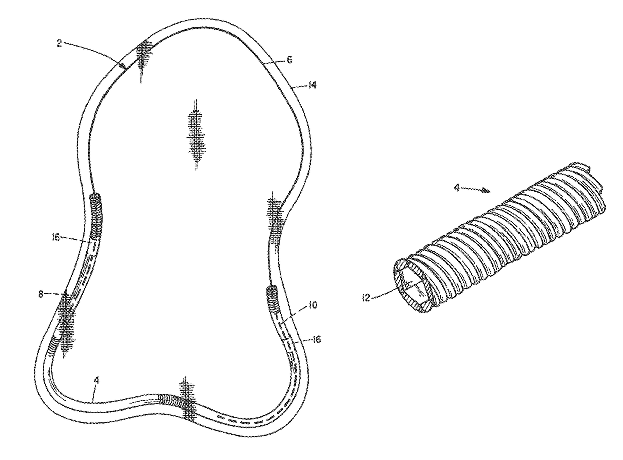
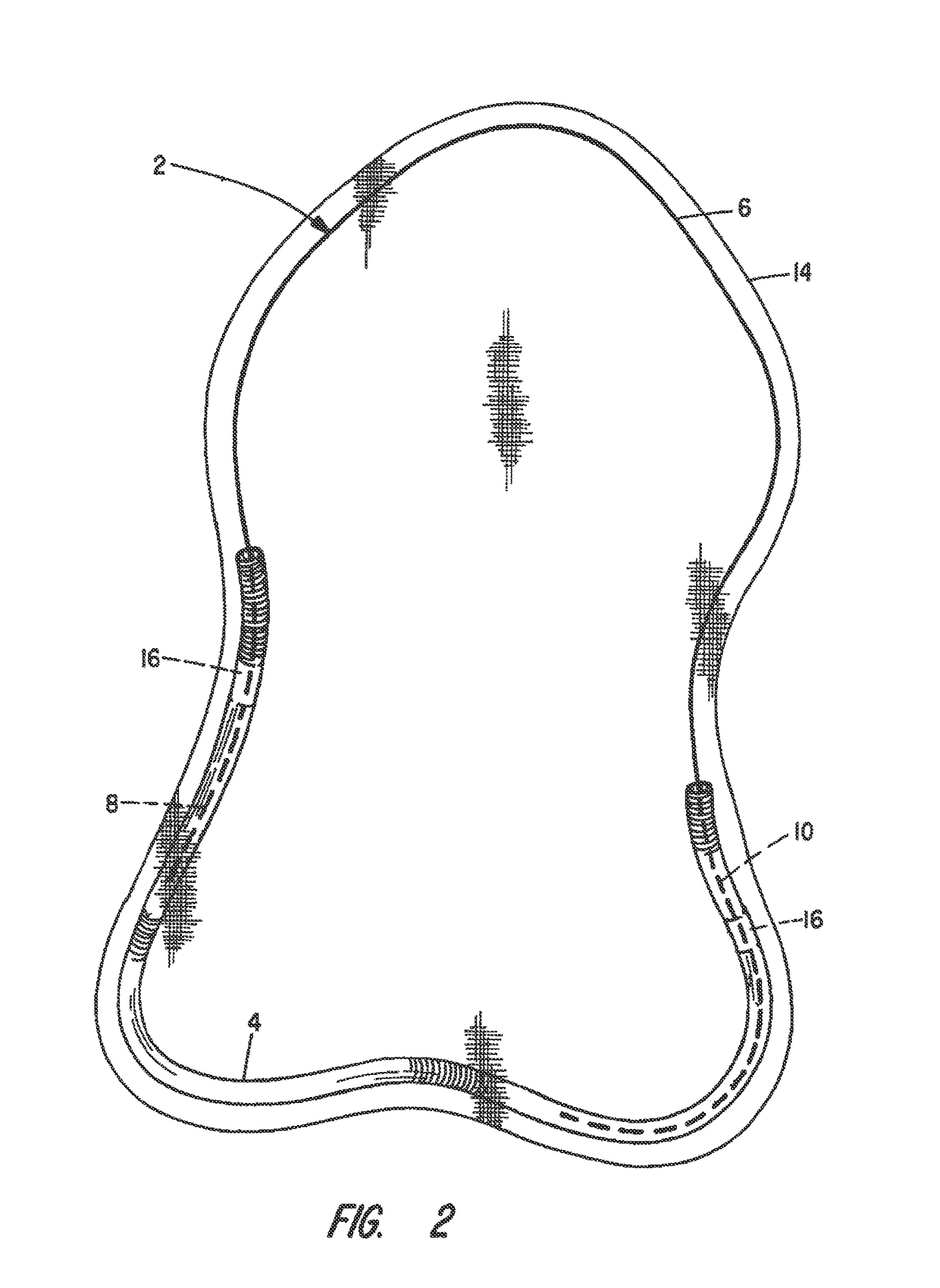
[0009]In accordance with the present invention, a hernia repair prosthesis comprises a segmented frame supporting a prosthetic mesh fabric, the frame forming a closed loop where first segments of the frame comprise helical, hollow, tubular metal strands and second segments comprise solid metal strands. In forming the frame, end portions of the second segments are inserted into end portions of the first segments and are dimensioned to be slidable therein. However, a bio-absorbable polymer is initially provided between the end portions of the second segments on the internal wall defining the tubular lumen of the first segments to create an interference fit that inhibits sliding. A prosthetic fabric is attached to the segmented frame. Following surgical implant and degradation of the polymer by body fluids at a time following stabilization of the hernia repair patch through tissue ingrowth through the mesh, the segments become free to move relative to one another and any stresses that might have been otherwise created in the frame are resolved in that the frame segments are permitted to move telescopically with respect to one another so that flexure of the frame at what would otherwise be a stress point is avoided.

Problems solved by technology

It was found that this prosthesis was somewhat difficult to deliver through a trocar of a sufficiently small diameter felt appropriate for use in typical endoscopic hernia repair surgery.

Method used


Image

  • Hernia patch frame incorporating bio-absorbable material
  • Hernia patch frame incorporating bio-absorbable material
  • Hernia patch frame incorporating bio-absorbable material

Examples


Embodiment Construction

[0015]This description of the preferred embodiments is intended to be read in connection with the accompanying drawings, which are to be considered part of the entire written description of this invention. In the description, relative terms such as “lower”, “upper”, “horizontal”, “vertical”, “above”, “below”, “up”, “down”, “top” and “bottom” as well as derivatives thereof (e.g., “horizontally”, “downwardly”, “upwardly”, etc.) should be construed to refer to the orientation as then described or as shown in the drawings under discussion. These relative terms are for convenience of description and do not require that the apparatus be constructed or operated in a particular orientation. Terms such as “connected”, “connecting”, “attached”, “attaching”, “join” and “joining” are used interchangeably and refer to one structure or surface being secured to another structure or surface or integrally fabricated in one piece, unless expressively described otherwise.

[0016]In FIG. 1 the frame port...


PUM

PropertyMeasurementUnit
inner diameteraaaaaaaaaa
outer diameteraaaaaaaaaa

Abstract

A hernia repair prosthesis comprises a segmented frame forming a closed loop where a first segment comprises a helical hollow tube and a second segment comprises a solid strand. Both segments are preferably a metal exhibiting shape memory properties and the two segments are assembled with end portions of the second segment inserted into the lumen at opposed end portions of the first segment with a clearance fit. At manufacture, a covering layer of a bio-absorbable polymer on the end portions of the second strand is sufficiently sized to create a temporary interference fit between the two segments to inhibit relative movement between them. The ability of the intercoupled segment to move relative to one another is restored upon degradation of the polymer due to exposure to body fluids following implantation of the prostheses. A prosthetic fabric is attached to the segmented frame.

Description

CROSS-REFERENCED TO RELATED APPLICATIONS[0001]Not applicable.STATEMENT OF GOVERNMENT INTEREST[0002]Not applicable.BACKGROUND OF THE INVENTION[0003]Field of the Invention[0004]This invention relates generally to a prosthesis for the repair of hernias, and more particularly to an improved hernia repair patch, deliverable in a rolled form through a trocar in an endoscopic procedure and which deploys, when unconstrained, to a somewhat planar configuration.[0005]Discussion of the Prior Art[0006]In U.S. Pat. No. 5,824,082, I disclose a hernia repair patch comprising a single strand, closed loop, wire frame made of a shape memory alloy on which is attached a prosthetic mesh. That device was intended for deployment through a trocar in the course of an endoscopic hernia repair procedure. It was found that this prosthesis was somewhat difficult to deliver through a trocar of a sufficiently small diameter felt appropriate for use in typical endoscopic hernia repair surgery.[0007]I later learne...

Claims


Application Information

Patent Timeline
Patent Type & Authority Patents(United States)
IPC IPC(8): A61F2/02A61F2/00
CPCA61F2/0063A61F2210/0004A61F2210/0014A61F2210/0019A61F2220/005A61F2220/0033A61F2220/0058A61F2220/0075A61F2250/0065
Inventor BROWN, RODERICK B.
Owner BROWN RODERICK B
Learn More