Generation of instructions for repairing an electromechanical system

a technology for electromechanical systems and instructions, applied in the field of electromechanical systems, can solve problems such as limited system us

Active Publication Date: 2017-06-20
SAP AG
View PDF10 Cites 3 Cited by
  • Summary
  • Abstract
  • Description
  • Claims
  • Application Information

AI Technical Summary

Benefits of technology

[0021]In some examples the data transfer system or a separate aggregator aggregates the measurement data. For example if a sensor is continuously acquiring sensor measurements which is the measurement data this may cause an increasingly large amount of data to be generated. A data aggregator could for instance take an average or statistical property of the measurement data for a particular period of time. This may reduce the amount of data that needs to be stored.
[0032]In another embodiment the historical data is displayed as a contour plot or a heat map. This may be beneficial because it may help the user to identify trends in the historical data.
[0033]In another embodiment the historical data is displayed as a scatter plot. The use of a scatter plot may be beneficial because is may help a user to identify failure modes.

Problems solved by technology

These systems are however of limited use, because they demand such a high amount of manual maintenance that they are not typically used.

Method used


Image

  • Generation of instructions for repairing an electromechanical system
  • Generation of instructions for repairing an electromechanical system
  • Generation of instructions for repairing an electromechanical system

Examples


Embodiment Construction

[0054]Like numbered elements in these figures are either equivalent elements or perform the same function. Elements which have been discussed previously will not necessarily be discussed in later figures if the function is equivalent.

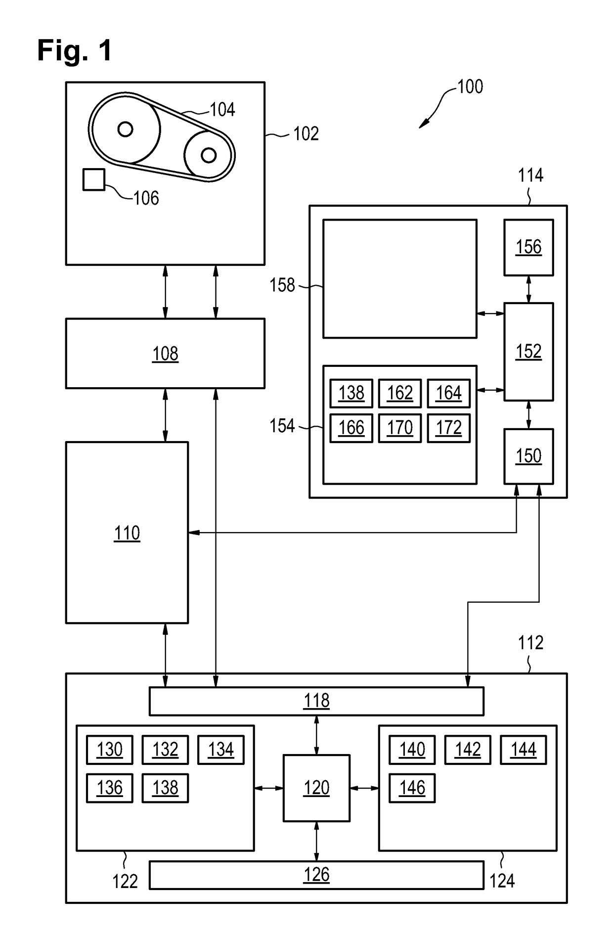
[0055]FIG. 1 illustrates an example of an electromechanical system 100. The electromechanical system comprises a machine 102. The machine 102 has at least one mechanical component 104 and a sensor 106 for monitoring the mechanical component. The electromechanical system 100 further comprises a data transfer system 108, a data logger 110, a machine monitor 112 and a client system 114.

[0056]The data transfer system is shown as receiving data from the sensor 106. The data transfer system 108 is able to transfer data to the data logger 110 and / or the machine monitor 112. In some cases the data transfer system may also function as a data aggregator particularly in situations where the sensor 106 or sensors produce large volumes of data. The data aggregator m...


PUM


Abstract

The invention provides for an electromechanical system comprising a machine. The machine comprises at least one mechanical component and at least one electrical sensor for acquiring measurement data. The system further comprises a data logger computer system for logging the measurement data and error reports as historical data, wherein the error reports are descriptive of one or more failure modes of the at least one mechanical component, wherein the error reports are further descriptive of repair actions taken to repair the one or more failure modes. The system further comprises a machine monitor comprising a repair solution engine, wherein the machine monitor comprises a memory containing processor instructions that implement the repair solution engine, wherein the machine monitor comprises a processor for executing the processor instructions. The system further comprises a data transfer system for transferring the data from the machine to the machine monitor. The system further comprises a client computer system. Execution of the processor instructions cause the processor to: receive the measurement data from the data transfer system; receive the historical data from the data logger computer system; search the historical data to determine a current failure mode and a selected repair action, wherein the current failure mode is selected from the one or more failure modes of the historical data, wherein the selected repair action is selected from the repair actions; generate repair instructions using the selected repair action; and transfer the repair instructions of the selected repair entry to the client computer system.

Description

BACKGROUND OF THE DISCLOSURE[0001]Field of the Disclosure[0002]The invention relates to electromechanical system, in particular for the generation of instructions for repairing electromechanical systems.[0003]Description of the Related Art[0004]For maintaining complex systems such as aircraft or factories, information system may be used to track maintenance schedules and keep records of actual maintenance that has been performed. Systems also exist which can keep a database of solutions for solving repair problems. These systems are however of limited use, because they demand such a high amount of manual maintenance that they are not typically used.SUMMARY OF THE PRESENT DISCLOSURE[0005]The invention provides for an electromechanical system, a machine monitor and a method of repairing the electromechanical system in the independent claims. Embodiments are given in the dependent claims.[0006]As will be appreciated by one skilled in the art, aspects of the present invention may be emb...

Claims


Application Information

Patent Timeline
Patent Type & Authority Patents(United States)
IPC IPC(8): G06F11/00G06F11/07G06F17/40
CPCG06F11/0766G06F11/0739G06F17/40
Inventor KLEIN, JAN PATRICKSEIDL, MARKUS
Owner SAP AG
Why Eureka
Try Eureka