Flow control device and method
a flow control and conduit technology, applied in the direction of sealing/packing, wellbore/well accessories, instruments, etc., can solve the problems of increasing the ability, increasing the cost of external control and force, and limited reservoir contact per well, so as to increase the degree of production and production cost
- Summary
- Abstract
- Description
- Claims
- Application Information
AI Technical Summary
Benefits of technology
Problems solved by technology
Method used
Image
Examples
Embodiment Construction
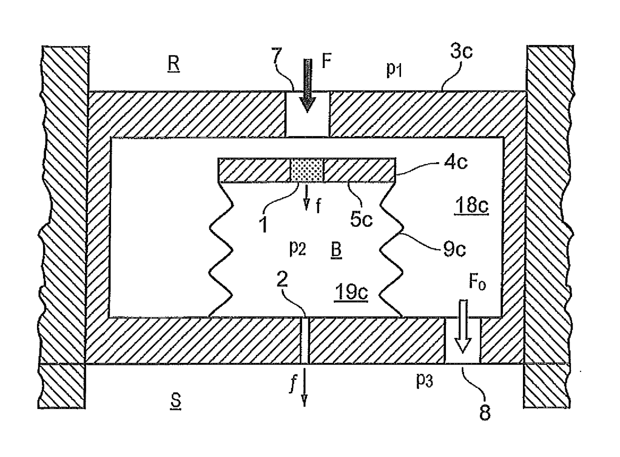
[0065]FIG. 1a illustrates how a fluid F flows into a conduit 3a at a first pressure p1, through a first flow restrictor 1 and into a chamber B where it attains a second pressure p2, and then flows through a second fluid flow restrictor 2 before it exits the conduit 3a at a third pressure p3. When the fluid flow rate and fluid properties (e.g. viscosity, density) are constant, the pressures (p1, p2, p3) are constant, and p1, >p2, >p3.
[0066]In FIG. 1a, the first flow restrictor 1 is a porous element and the second flow restrictor 2 is an orifice.
[0067]In general, the flow characteristics through a porous medium may be described using Darcy's law (i.e. laminar flow), expressed as:
[0068]Q=κperm·Aμ·ΔPΔL(Equation1)
where: Q=fluid flow rate (units of volume per unit time)[0069]Kperm=relative permeability of the porous medium (typical unit: Darcy)[0070]A=cross-sectional area of the porous medium[0071]μ=viscosity of the fluid (typical unit: centipoise; SI unit: Pa*s)[0072]ΔP=differentia...
PUM
 Abstract
Description
Claims
Application Information
 - R&D
- Intellectual Property
- Life Sciences
- Materials
- Tech Scout
- Unparalleled Data Quality
- Higher Quality Content
- 60% Fewer Hallucinations
Browse by: Latest US Patents, China's latest patents, Technical Efficacy Thesaurus, Application Domain, Technology Topic, Popular Technical Reports.
© 2025 PatSnap. All rights reserved.Legal|Privacy policy|Modern Slavery Act Transparency Statement|Sitemap|About US| Contact US: help@patsnap.com


