
Stator for a high-temperature electric motor and electric motor

a high-temperature electric motor and electric motor technology, applied in the direction of winding insulation shape/form/construction, electrical apparatus, manufacturing dynamo-electric machines, etc., can solve the problems of motor not being able to be set up, motor assembly complicated, electric motor manufacturing described, etc., and achieve the effect of being easy to manufacture and sufficiently stabl

Inactive Publication Date: 2017-05-23
MAXON MOTOR AG
View PDF24 Cites 3 Cited by
  • Summary
  • Abstract
  • Description
  • Claims
  • Application Information

AI Technical Summary

Benefits of technology

The patent aims to improve the design of the stator to make it easy to make and stable for high-temperature applications.

Problems solved by technology

The stator winding interconnection described in DE 10 2004 050374 A1 requires a specific configuration of the electric motor housing, thus necessitating a complicated manufacture of the housing.
In addition, the motor cannot be set up without this specifically configured housing.
The manufacture of the electric motor described in DE 10 2011 100863 A1 and DE 10 2011 100843 A1 is relatively complicated as the rail parts configured in the form of annulus sections have to be spaced apart from each other with exact distances there between prior to encapsulating them, together with the stator winding, by the electrically insulating encapsulating material.

Method used


Image

  • Stator for a high-temperature electric motor and electric motor
  • Stator for a high-temperature electric motor and electric motor
  • Stator for a high-temperature electric motor and electric motor

Examples


Embodiment Construction

[0035]In the description below like components will be designated with like reference numbers. If reference numbers are shown in an illustration which will not be referred to in the associated description of the figures, reference is made to preceding or following descriptions of figures.

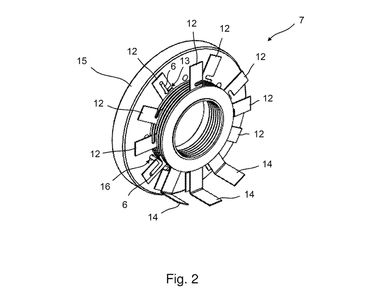
[0036]FIG. 1 shows a longitudinal section through a small-power electric motor configured for high-temperature applications up to 550° C. Merely the housing 17 and the stator 1 of the electric motor 2 are illustrated. The rotor of the electric motor is not illustrated in the figure. The stator comprises a hollow-cylindrical ironless stator winding 3 which is surrounded by an equally hollow-cylindrically configured magnetic back yoke 18. The outer back yoke 18 is adjacent to the outer circumference of the ironless stator winding 3. The stator winding 3 and the back yoke 18 are, therefore, arranged coaxially to each other and have the common axis 4. The stator winding 3 is configured to be substantial...


PUM


Abstract

A stator for an electric motor for use at very high temperatures of up to 550° C. is provided, comprising a stator winding with an axis and with several winding wire ends which are passed out at a front end of the stator winding. The stator further comprises a stator winding interconnection with several ring conductors which are arranged at the front end of the stator winding coaxially to same and are axially spaced apart from each other. The ring conductors serve the electrical contacting of the winding wire ends. It is provided that an electrically insulating distance ring is respectively provided between axially successive ring conductors, wherein the ring conductors and the distance rings are alternately stacked.

Description

CROSS-REFERENCE TO RELATED APPLICATION[0001]This application claims priority to foreign European Patent Application EP 13001589.4, filed on Mar. 27, 2013, the disclosure of which is incorporated herein by reference in its entirety.FIELD OF THE INVENTION[0002]The present invention relates to a stator for an electric motor according to the preamble of independent claim 1.[0003]A stator of this type comprises a stator winding with an axis and with several winding wire ends passed out at a front end of the stator winding. The stator further comprises a stator winding interconnection with several ring conductors arranged at the front end of the stator winding coaxially to same and being axially spaced apart from each other. The ring conductors are provided to electrically contact the winding wire ends.BACKGROUND[0004]An electric motor with a stator winding interconnection comprising several ring conductors is known from DE 10 2004 050374 A1. The electric motor is configured as an inner r...

Claims


Application Information

Patent Timeline
Patent Type & Authority Patents(United States)
IPC IPC(8): H02K15/12H02K3/28H02K3/38
CPCH02K3/28H02K3/38H02K2203/09
Inventor BRZUSKA, YAAQUBKUNSTMANN, KORNELIAASCHWANDEN, PIAHANNI, TOBIASHAGE, BERNDFURDERER, BERND
Owner MAXON MOTOR AG
Learn More