
Cable connector assembly with improved indication effect

a technology of indication effect and cable connector, which is applied in the direction of coupling device connection, electrical apparatus, two-part coupling device, etc., to achieve the effect of improving the indication

Active Publication Date: 2017-05-23
FOXCONN INTERCONNECT TECH LTD
View PDF37 Cites 18 Cited by
  • Summary
  • Abstract
  • Description
  • Claims
  • Application Information

AI Technical Summary

Benefits of technology

The present invention is about a cable connector assembly that has improved indication effects. The technical effect of this invention is to make it easier for users to identify the connection and ensure proper functionality.

Problems solved by technology

Therefore, users need to turn on the apparatus for viewing the charging status, which is inconvenient.

Method used


Image

  • Cable connector assembly with improved indication effect
  • Cable connector assembly with improved indication effect
  • Cable connector assembly with improved indication effect

Examples


Embodiment Construction

[0016]Referring to FIG. 1, a cable connector assembly 100 in accordance with the present invention comprises a first connector 10 for connecting with a mobile phone and other mobile electronic devices, a second connector 20 connecting to a power source and a cable 210 electrically connected between the first connector 10 and the second connector 20. In present embodiment, the first connector is a lightning connector; the second connector is a USB connector. In other embodiments, the first connector 10 can be other types of connectors.

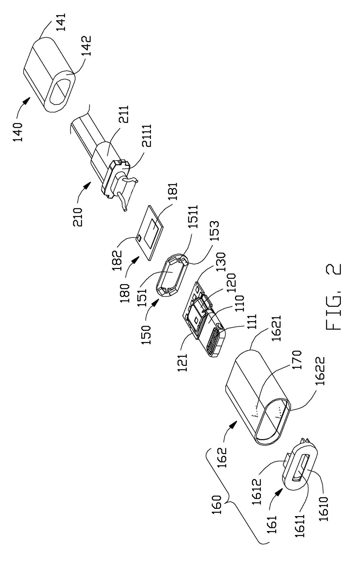
[0017]Referring to FIG. 2, the first connector includes a main body 110, a number of contacts 111 retained in the main body 110 and exposed on two opposite sides of a front end of the main body 110 to commonly form a mating member, a first / horizontal circuit board 130 assembled on a rear end of the main body 110 and electrically connected to the contacts 111, a metal shell 120 enclosing the first circuit board 130, a second circuit board 180 fixed paral...


PUM


Abstract

A cable connector assembly (100) includes: a cable (30) having a number of inner wires; a first connector (10) including a main body (120), plural contacts (121) retained in the main body, a first circuit board (130), a luminous element (152), and a cover; and a second circuit board (180) assembled on a rear end of the first circuit board and getting power and grounding source from the first circuit board. The second circuit board includes a detection contact (182) electrically connected to an inner wire of the cable, and a chip (181) electrically connected respectively to the luminous element and the detection contact. The chip detects a voltage difference between the power source and the first connector. A light is emitted by the luminous element passing through the cover to indicate a charging status of the charging device.

Description

BACKGROUND OF THE INVENTION[0001]1. Field of the Invention[0002]The present invention relates to a cable connector assembly, and more particularly to a cable connector assembly having a luminous element to indicate charging status of a charging apparatus.[0003]2. Description of Related Art[0004]A cable connector assembly is usually used to charge a rechargeable battery of a mobile electronic device. Cable connector assemblies usually do not have an indicator to indicate the charging status of a charging apparatus. Therefore, users need to turn on the apparatus for viewing the charging status, which is inconvenient.[0005]China Publication No. 102647014 discloses a cable structure with an indicating function, which is composed of a cable, a first connector plug, and an indication unit, wherein: the first connector plug is provided with a main body part and a connection part and is coupled with one end of the cable; the indication unit is fixedly arranged in the main body part and is p...

Claims


Application Information

Patent Timeline
Patent Type & Authority Patents(United States)
IPC IPC(8): H01R3/00H01R13/717H01R13/66H01R24/60H01R31/06
CPCH01R13/7175H01R13/6675H01R31/065H01R24/60
Inventor CHEN, CHI-MINGZHANG, DE-GANGLI, ZHI-YANG
Owner FOXCONN INTERCONNECT TECH LTD
Learn More