Cupboard with up-down louvered door and balance system
a louvered door and up-down technology, applied in the direction of door/window protective devices, furniture parts, shutters/movable grilles, etc., can solve the problems of difficult to take out, difficult to place a big article in the center, inconvenience, etc., to facilitate taking out/putting in articles, simple structure, good stability
- Summary
- Abstract
- Description
- Claims
- Application Information
AI Technical Summary
Benefits of technology
Problems solved by technology
Method used
Image
Examples
embodiment 1
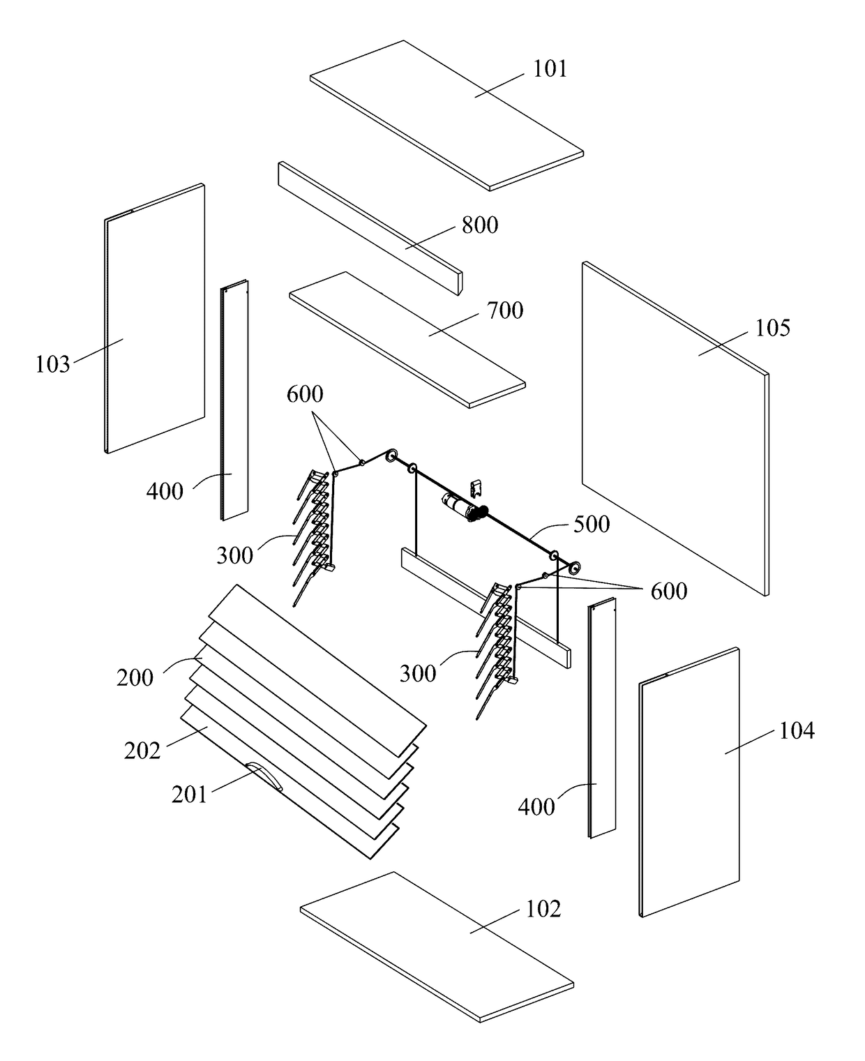
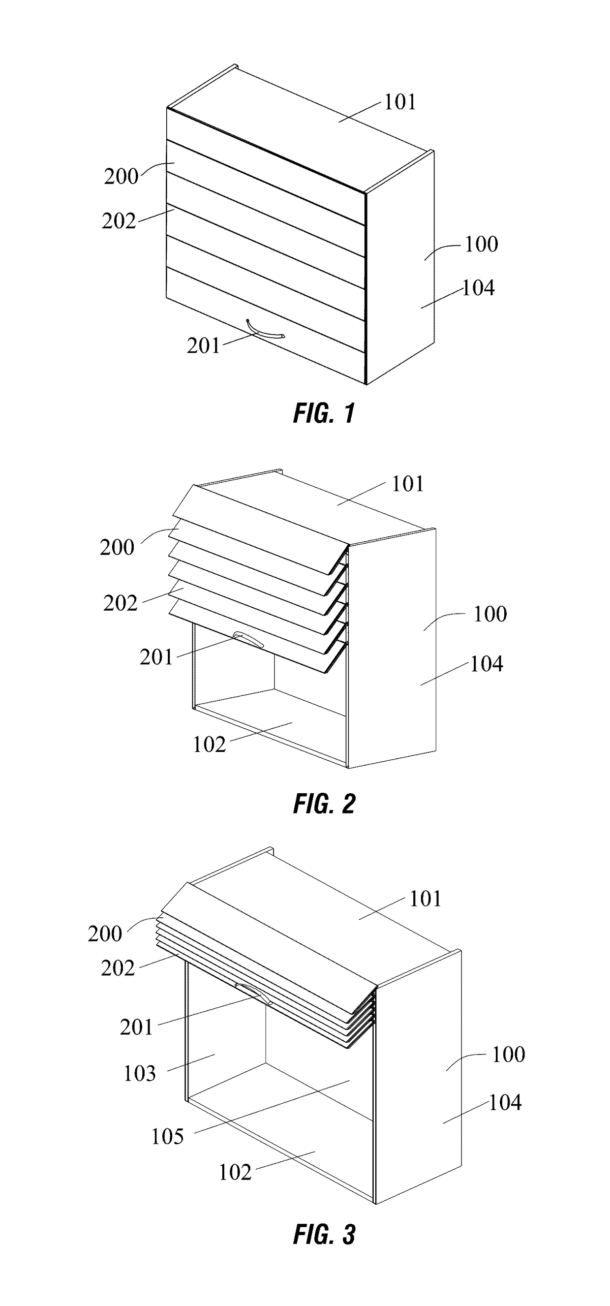
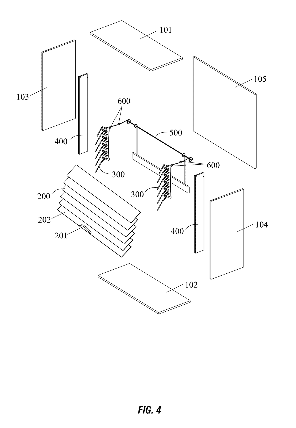
[0047]A cupboard with up-down louvered door is shown in FIGS. 1-12.
[0048]The cupboard with up-down louvered door comprises a cupboard body or box 100 with an open front, a door 200 on the body 100 movable between a raised open position and a lowered closed position, and a handle 201 mounted on the door 200.
[0049]The door 200 adopts a lift louvered mechanism, comprising a plurality of louvers 202, a pair of lift racks 300, and a guideway 400 for each lift rack 300.
[0050]Each of the lift racks 300 comprises a plurality of first lift units 310, and a plurality of second lift units 320 in which each second lift unit 320 is connected to two adjacent first lift units 310. Each louver 202 is secured to each corresponding first lift unit 310.
[0051]Each first lift unit 310 comprises a first connective element or finger 311 securing to the louver 202, and a second connective element 312 hinged to the first connective element 311. Each second lift unit 320 comprises a third connective element ...
embodiment 2
[0058]In an alternative embodiment of the invention shown in FIGS. 4-5, the cupboard also includes a balance system 500 comprising a transmission shaft 501, a first pair of pulleys 502 on the transmission shaft 501, and a weight or balance component.
[0059]The first pair of pulleys 502 are connected to a pair of rack belts 503. One end of each rack belt 503 is secured to each pulley 502, and the other end of each rack belt 503 is connected to the lift racks 300, specifically to the second connective element 312 which is located at a lowest end of the lift racks 300, such that the door 200 is connected to the rack belts 503, and provides the rack belts 503 with a pulling force due to the weight of the door 200.
[0060]The balance component comprises a balancing member or weight 506, a pair of balancing belts 505 and a second pair of pulleys 504 on the transmission shaft 501. One end of each of the balancing belts 505 are connected to the second pulleys 504, and the other end of each of ...
embodiment 3
[0066]In another alternative embodiment shown in FIGS. 11-12, the cupboard also includes a motor transmission apparatus which is mounted in a mounting plate 700 located beneath the top board 101. A baffle plate 800 is also set up in the body 100.
[0067]The motor transmission apparatus comprises a motor 507, a first gear 508 coaxially connected to the motor 507, and a second gear 509 secured to the transmission shaft 501. The first gear 508 engages with the second gear 509. Preferably the second gear 509 is arranged at the center of the transmission shaft 501.
[0068]An electric / manual switch 510 is operatively connected to the motor 507, for enabling the first gear 508 and the second gear 509 to be disengaged / engaged. When the first gear 508 and the second gear 509 are disengaged, the balance system will be in a manual state, wherein a small driving force to the handle, places the system in imbalance to open / close the door.
[0069]When the first gear 508 and the second gear 509 are engag...
PUM
 Abstract
Description
Claims
Application Information
 - R&D
- Intellectual Property
- Life Sciences
- Materials
- Tech Scout
- Unparalleled Data Quality
- Higher Quality Content
- 60% Fewer Hallucinations
Browse by: Latest US Patents, China's latest patents, Technical Efficacy Thesaurus, Application Domain, Technology Topic, Popular Technical Reports.
© 2025 PatSnap. All rights reserved.Legal|Privacy policy|Modern Slavery Act Transparency Statement|Sitemap|About US| Contact US: help@patsnap.com


