Dispenser assembly for aerosol container

a technology for aerosol containers and dispensers, which is applied in the direction of transportation and packaging, packaging foodstuffs, packaged goods types, etc., can solve the problems of clogging the nozzle, content remaining in the nozzle may sometimes dry up, etc., and achieves the effect of convenient cleaning, convenient mounting, and convenient cleaning of the passage of contents

Active Publication Date: 2017-04-25
TOYO AEROSOL IND CO LTD
View PDF24 Cites 2 Cited by
  • Summary
  • Abstract
  • Description
  • Claims
  • Application Information

AI Technical Summary

Benefits of technology

[0015]According to the present invention, the dispenser assembly includes a fixing plate mounted to the aerosol container, a nozzle connected to the stems of the container, and a cover member having an operation part for pressing the nozzle and held by engagement with the fixing plate such as to cover the nozzle. The cover member includes a lower cover located immediately above the fixing plate and having a first engaging piece that engages with a first engaging hole provided to the fixing plate, and an upper cover having the operation part for pressing the nozzle and a second engaging piece that engages with a second engaging hole provided to the lower cover. These fixing plate, lower cover, nozzle, and upper cover can all be attached to the aerosol container in this order from the same direction (from above the aerosol container). Alternatively, the lower cover, nozzle, and upper cover may preliminarily be attached to the fixing plate in this order, after which the assembly may be attached to the aerosol container. Namely, these components can readily be mounted, since there is no work of attaching them from above and below a main tubular component as was conventionally done. The lower cover is provided with a pressing portion that is supported via a hinge and abuts on the second engaging piece to disengage the second engaging piece from the second engaging hole, so that, by pressing in this pressing portion, the upper cover can be removed, which in turn allows the nozzle to be removed from above. This way, the nozzle can be cleaned easily.
[0016]If the nozzle is a two-piece structure in which a lower member and an upper member are connected via a hinge such as to be opened and closed, the work of cleaning the passage of contents can be performed even more easily.
[0017]If an over cap is provided immediately above the upper cover such as to cover the discharge tube of the nozzle and the operation part, unintended discharging of the contents can be avoided since accidental pressing of the pressing portion can be effectively prevented. Also, the amount of dust or the like adhered to the discharge tube will be reduced so that the nozzle will need to be cleaned less frequently.
[0018]If the over cap includes a cap protrusion that detachably engages with a cover protrusion that is provided to the upper cover or the lower cover, the cap protrusion being provided at four positions, in the front and the back on both sides of an axial line of the discharge tube, the over cap can be retained more stably.

Problems solved by technology

In such a dual compartment aerosol container, the contents remaining in the nozzle may sometimes dry up and clog the nozzle.

Method used


Image

  • Dispenser assembly for aerosol container
  • Dispenser assembly for aerosol container
  • Dispenser assembly for aerosol container

Examples


Embodiment Construction

[0059]Hereinafter, the present invention will be described in more detail with reference to the drawings.

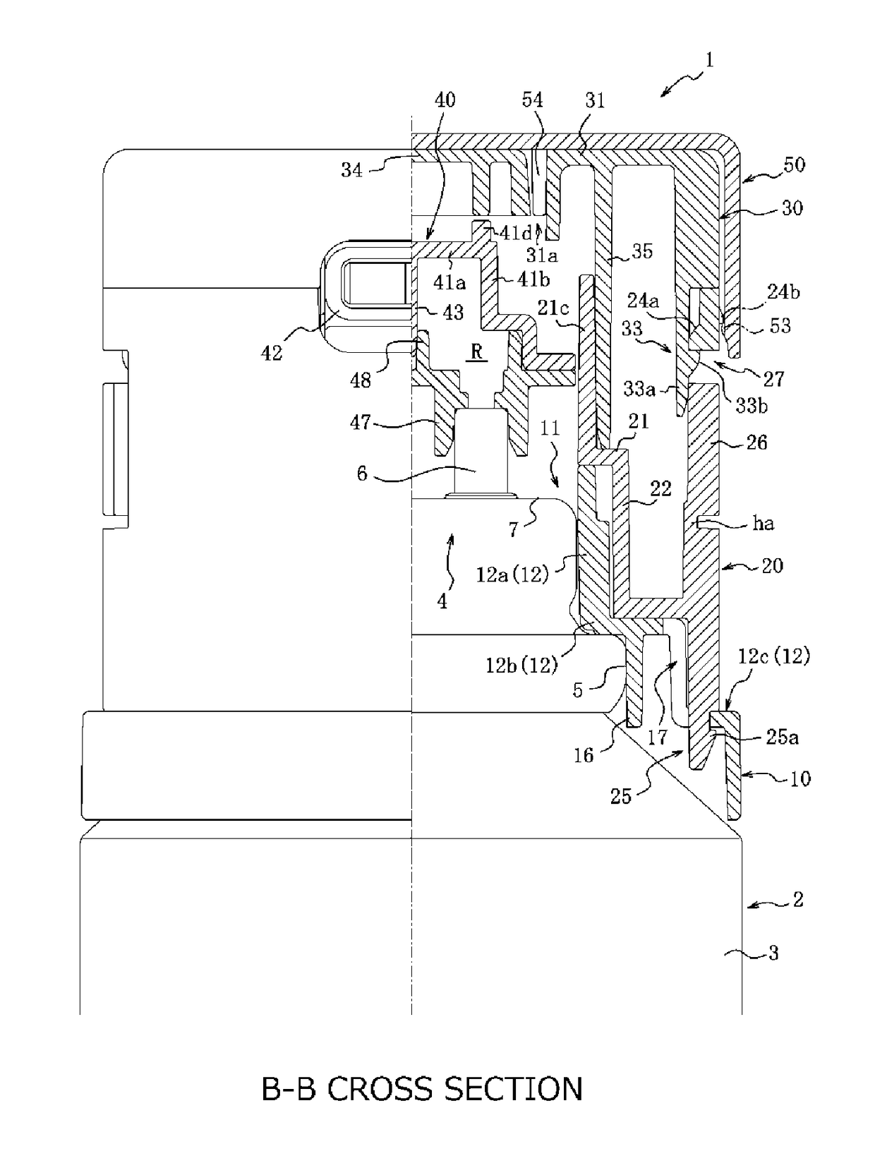
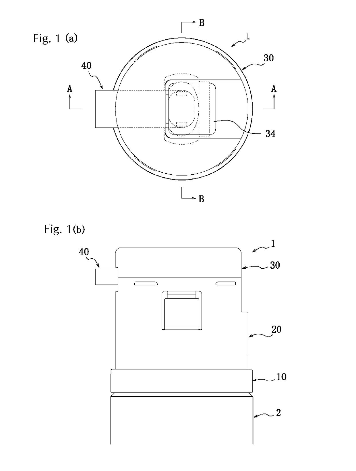
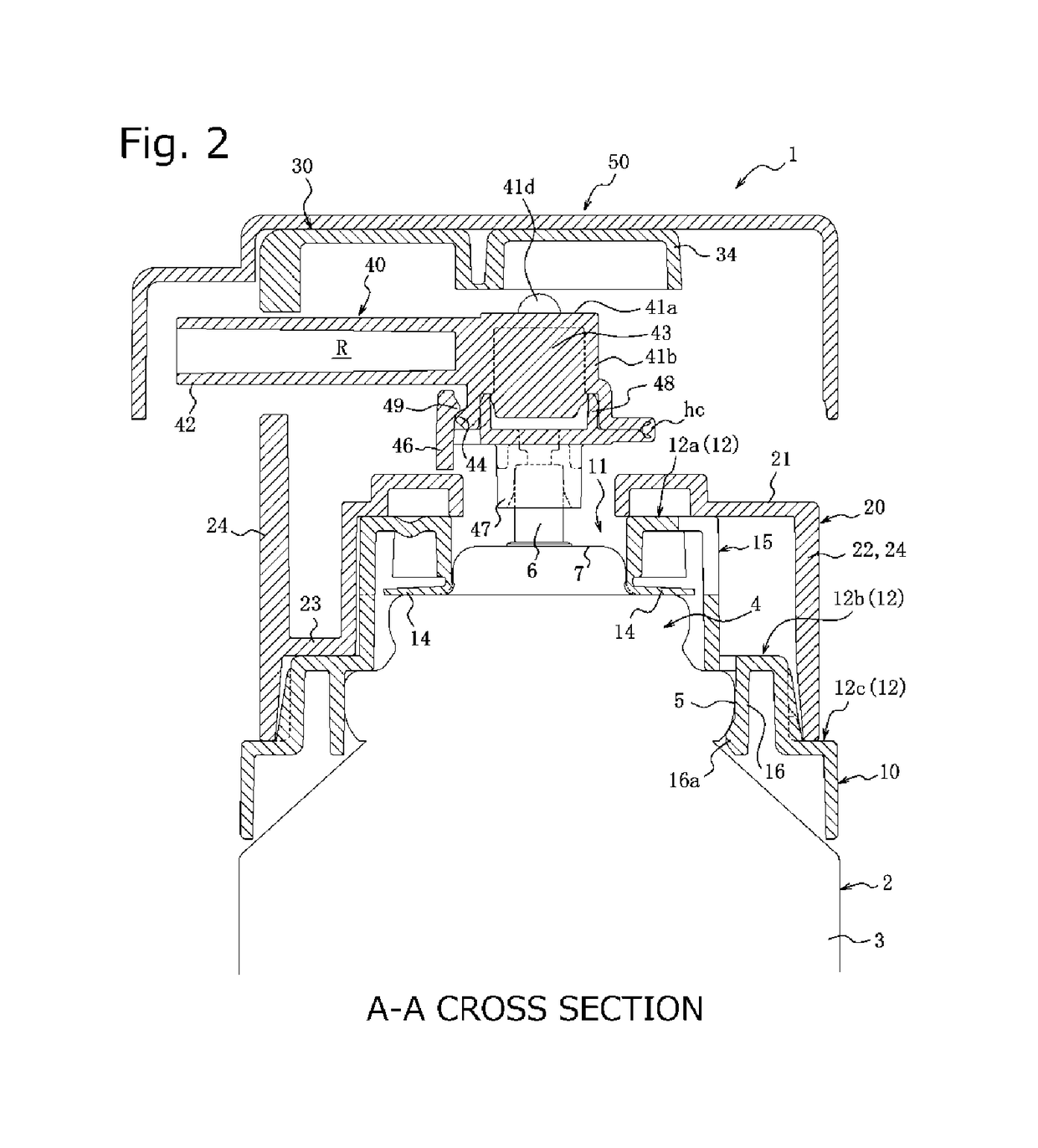
[0060]FIG. 1 illustrates an embodiment of the dispenser assembly for an aerosol container according to the present invention in a state in which the assembly is mounted to the container while the over cap is removed, where (a) is a plan view and (b) is a side view. FIG. 2 is an enlarged cross-sectional view of major parts along A-A shown in FIG. 1(a). FIG. 3 is an enlarged half cross-sectional view of major parts along B-B shown in FIG. 1(a). FIG. 4 illustrates the fixing plate shown in FIG. 1, where (a) is a plan view, (b) is a half cross-sectional view along C-C of (a), (c) is a cross-sectional view along D-D of (a), and (d) is a bottom view. FIG. 5 illustrates the lower cover shown in FIG. 1, where (a) is a plan view, (b) is a half cross-sectional view along E-E of (a), and (c) is a cross-sectional view along F-F of (a). FIG. 6 illustrates the lower cover shown in FIG. 1, wher...


PUM


Abstract

The dispenser assembly for an aerosol container includes a fixing plate 10 mounted to an aerosol container 2 that has two stems 6, a nozzle 40 for discharging the contents via two connection parts 47 that respectively lead to the stems 6 and via one discharge tube 42, and a cover member covering the nozzle 40 and held by engagement with the fixing plate 10. The cover member includes a lower cover 20 having a first engaging piece 25, and an upper cover 30 having a second engaging piece 33. The lower cover 20 has a pressing portion 26 that is supported via a hinge ha and pushes on the second engaging piece 33 to disengage the second engaging piece from the second engaging hole 27.

Description

TECHNICAL FIELD[0001]The present invention relates to a dispenser assembly for an aerosol container, the assembly including a fixing plate mounted to a mounting cup of the aerosol container, a nozzle having a discharge tube for discharging the content, and a cover member having an operation part for pressing the nozzle and held by engagement with the fixing plate, and more particularly to a dispenser assembly used for an aerosol container containing two types of contents separately and having a total of two stems for discharging the contents.BACKGROUND ART[0002]As one type of container that holds two-part type hair dyes or hair styling liquids or the like, a dual compartment aerosol container has hitherto been known (see, for example, Patent Document 1), which includes a pair of left and right aerosol containers, a nozzle having two connection parts that lead to the stems of respective aerosol containers and discharging the contents held in respective containers from one discharge t...

Claims


Application Information

Patent Timeline
Patent Type & Authority Patents(United States)
IPC IPC(8): B67D1/08B65D83/20B65D83/40A45D34/00B65D83/68B05B15/02
CPCB65D83/206A45D34/00B65D83/40B65D83/68B05B15/0208B05B15/52
Inventor OGATA, KENSHIMIZU, HIROKAZUTOMA, TORUFURUSAWA, MITSUOFUJIE, TAKASHI
Owner TOYO AEROSOL IND CO LTD
Why Eureka
Try Eureka