Apparatus and method for interpreting received control commands
a technology of control commands and apparatus, applied in the field of apparatus and method for interpreting control commands, can solve problems such as insufficient energy of control elements to differentia
- Summary
- Abstract
- Description
- Claims
- Application Information
AI Technical Summary
Benefits of technology
Problems solved by technology
Method used
Image
Examples
first embodiment
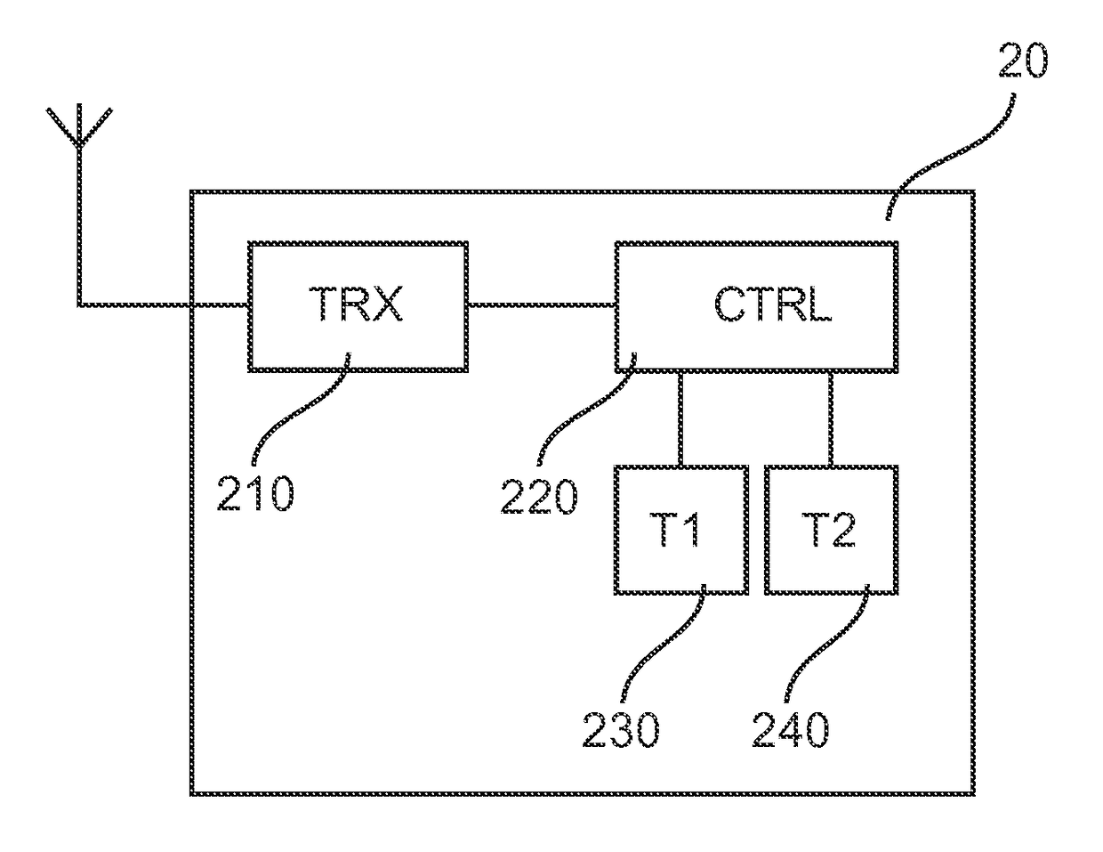
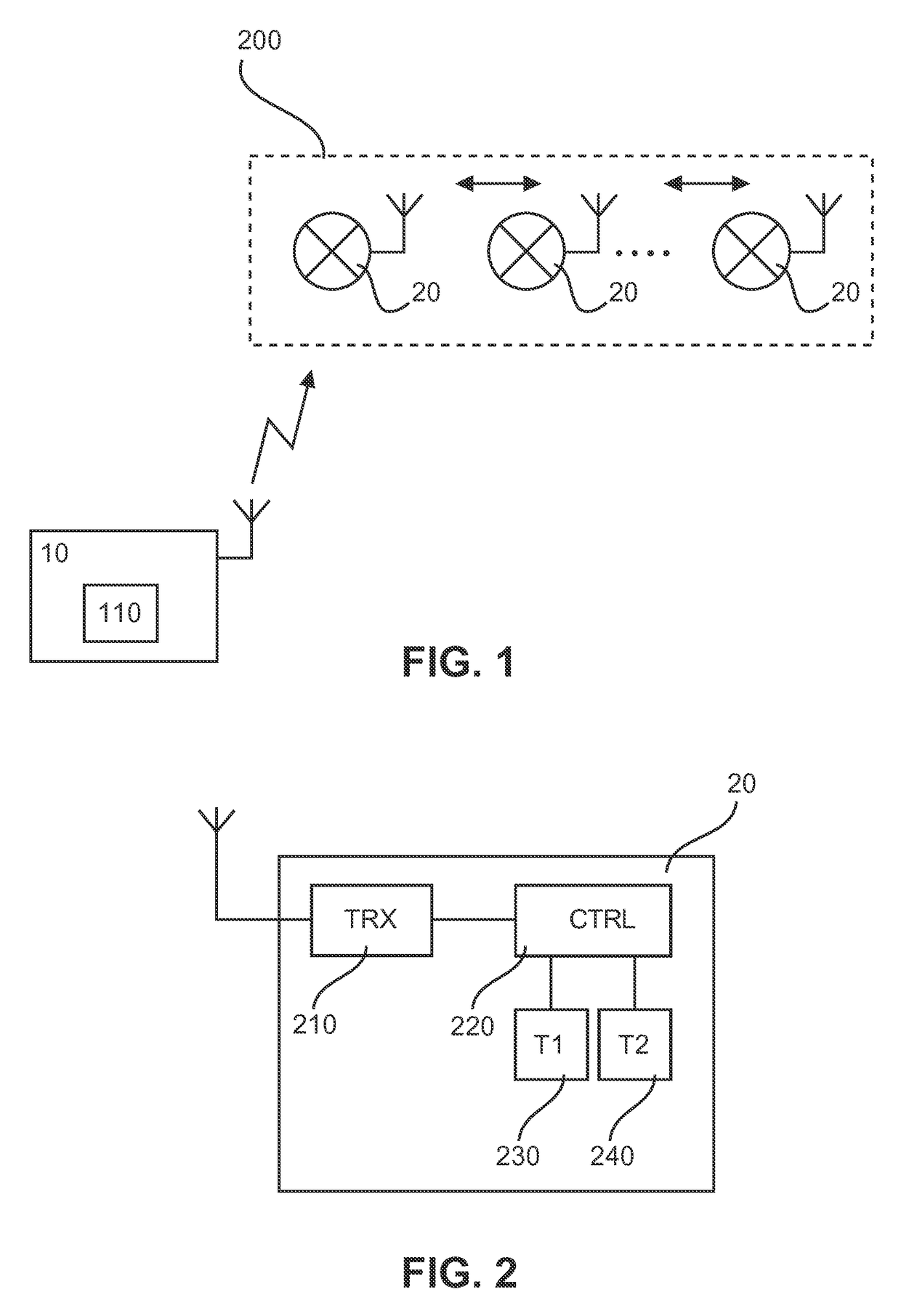
[0029]FIG. 2 shows a block diagram of a controlled device 20 according to a The controlled device 20 comprises a receiver or transceiver (combination of receiver and transmitter) 210 for receiving control commands via a radio channel of the communication network 200 of FIG. 1. Furthermore, the controlled device 20 comprises a processor unit 220 with a control logic or function for implementing the control interpretation and derived control actions by utilizing at least two time thresholds for a time interval between received raw control commands. The time thresholds are implemented by a first timer (T1) 230 and a second timer (T2) 240 connected to or implemented by the processor unit 220. The first timer 230 is adapted to count a lower time threshold (i.e. shorter time period) used for determining a short activation period (e.g., short button press) at the control element 10 based on received related control commands, so as to determine a corresponding derived control action. Addit...
second embodiment
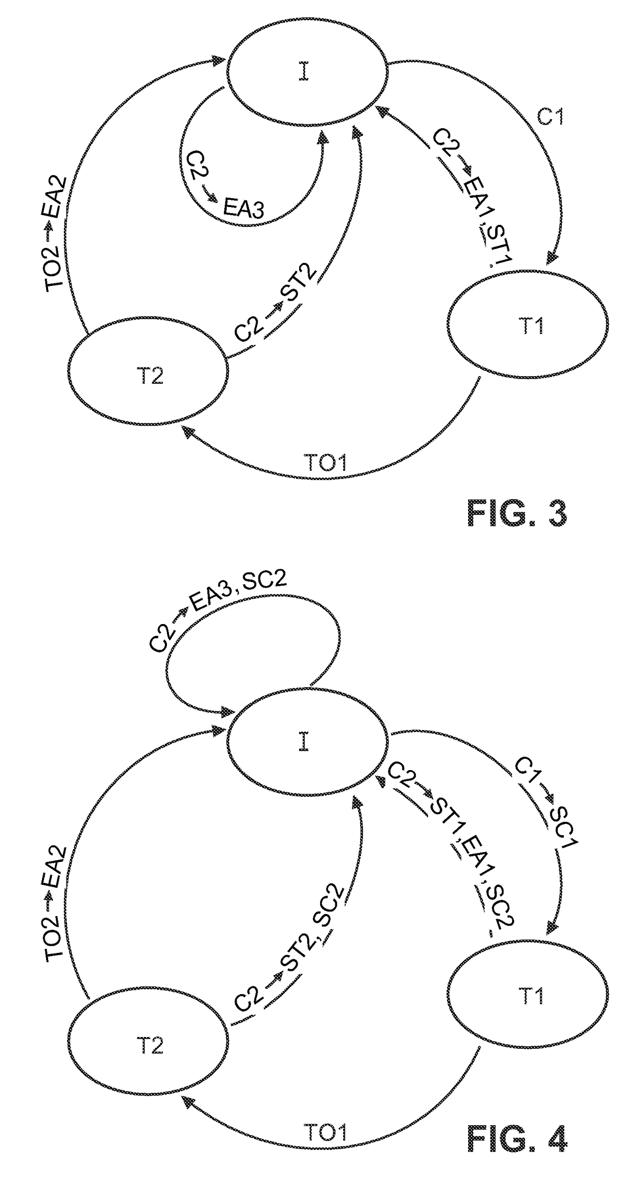
[0043]FIG. 4 shows a schematic state diagram of a state machine representation of a command interpretation processing with raw control command forwarding.
[0044]Initially, the procedure is in the idle state (first state) and waits for the receipt of the first command (C1). If C1 is received, the processing unit 220 initiates sending or forwarding of C1 to the communication network 200 (SC1) and starts the first timer 230, so that the second state T1 is entered. If C2 is received during the second state, the processing unit 220 initiates sending or forwarding of C2 to the communication network 200 (SC2) and execution of the first predetermined action (EA1), e.g., toggle action, and stops the first timer 230 (ST1), so that the idle state is entered again. If no C2 is received during the first timer operation, the processing unit 220 detects a time-out of the first timer 230 (TO1) and starts the second timer 240, so that the third state (T2) is entered. If C2 is received during the thi...
third embodiment
[0048]FIG. 5 shows a schematic state diagram of a state machine representation of a command interpretation processing with derived control action forwarding.
[0049]Initially, the procedure is in the idle state (first state) and waits for the receipt of the first command (C1). If C1 is received, the processing unit 220 starts the first timer 230, so that the second state T1 is entered. If C2 is received during the second state, the processing unit 220 initiates execution of the first predetermined action (EA1), e.g., toggle action, and sending or forwarding of a message or indication of the first predetermined action to the communication network 200 (SA1), and stops the first timer 230 (ST1), so that the idle state is entered again. If no C2 is received during the first timer operation, the processing unit 220 detects a time-out of the first timer 230 (TO1) and starts the second timer 240, so that the third state (T2) is entered. If C2 is received during the third state, the processi...
PUM
 Abstract
Description
Claims
Application Information
 - R&D
- Intellectual Property
- Life Sciences
- Materials
- Tech Scout
- Unparalleled Data Quality
- Higher Quality Content
- 60% Fewer Hallucinations
Browse by: Latest US Patents, China's latest patents, Technical Efficacy Thesaurus, Application Domain, Technology Topic, Popular Technical Reports.
© 2025 PatSnap. All rights reserved.Legal|Privacy policy|Modern Slavery Act Transparency Statement|Sitemap|About US| Contact US: help@patsnap.com


