
Food comminution device

a comminution device and food technology, applied in the field of food comminution devices, can solve the problems of not offering other possibilities for the comminution of food items, the actuation part cannot withstand relatively high loads, and the device does not allow relatively large food items that have not been previously sliced, etc., to achieve fast and efficient handling and compact design

Inactive Publication Date: 2017-03-21
GENIUS GMBH
View PDF19 Cites 2 Cited by
  • Summary
  • Abstract
  • Description
  • Claims
  • Application Information

AI Technical Summary

Benefits of technology

[0011]It is therefore the object of the present invention to specify a food comminution device which makes it possible for food items to be comminuted in different ways, and which can furthermore be handled quickly and efficiently and which can be of compact design.

Problems solved by technology

Said devices do not offer other possibilities for the comminution of food items.
However, the device has the particular disadvantage that, owing to the integrated slicer, the actuation part cannot withstand relatively high loads during the pressing of items for comminution through the cutting grate.
Said device does not allow relatively large food items that have not been previously sliced, such as for example relatively large potato pieces, to be pushed through.

Method used


Image

  • Food comminution device
  • Food comminution device
  • Food comminution device

Examples


Embodiment Construction

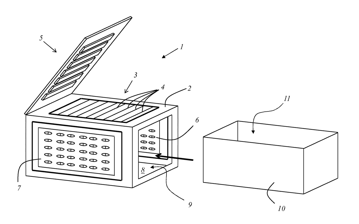
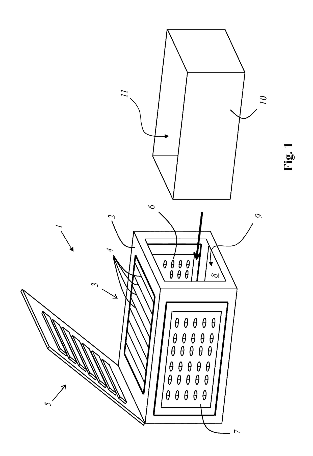
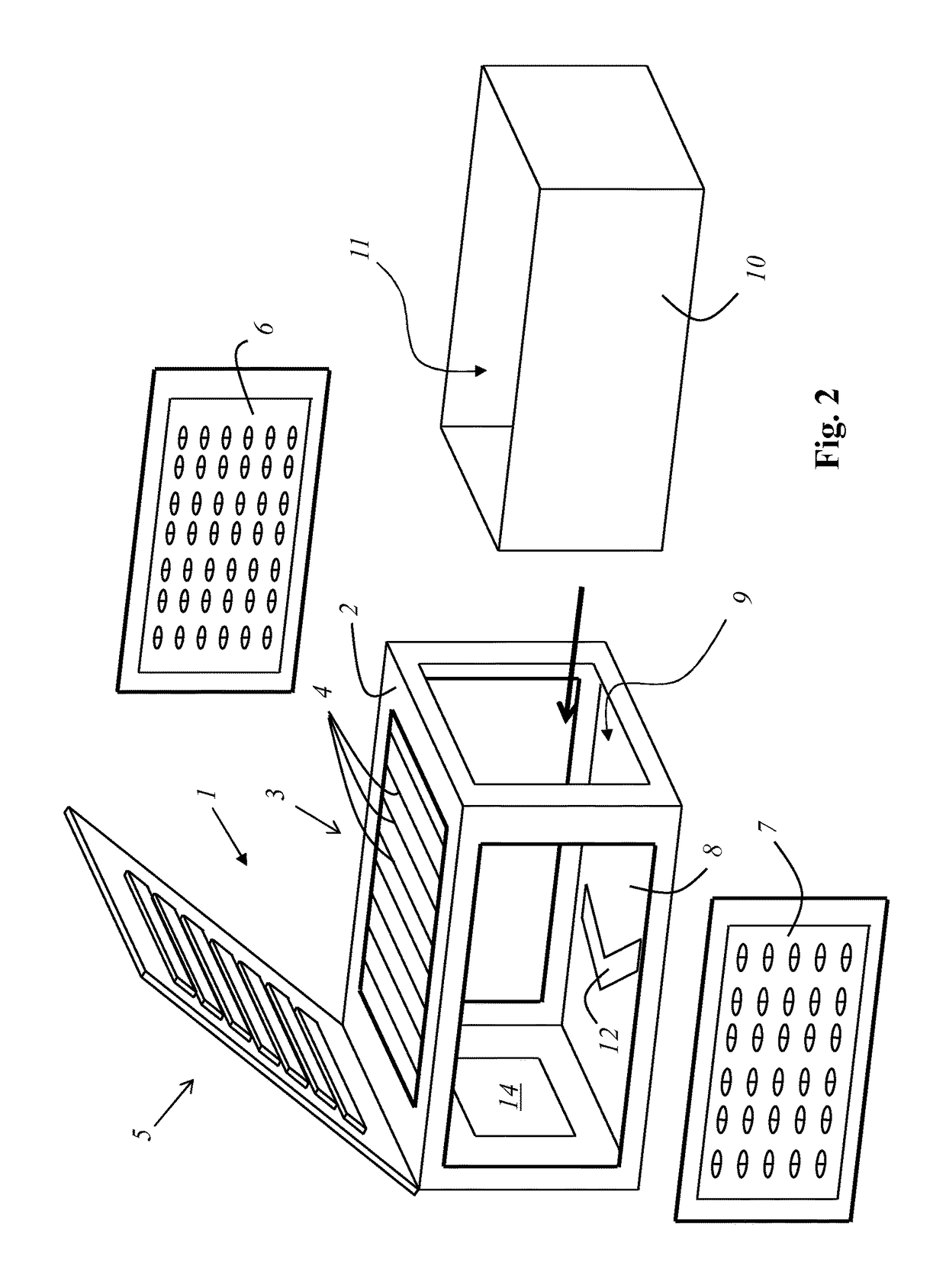
[0094]FIG. 1 shows an exemplary embodiment of a food comminution device according to the invention in a first setting-down orientation for the use of a first comminution tool 1. The food comminution device has a base part 2 which, as an outer contour, has the outer contour of a cuboid. The base part 2 bears a removable cutting part 3 which has multiple cutting blades 4. Also articulatedly fixed to the base part is an actuation part 5 which, for pushing food items for comminution through the cutting part 3, can be pivoted from a loading position toward the cutting part 3 into a closed position and subsequently from the closed position back into the loading position. The cutting part 3 and the actuation part are constituent parts of the first comminution tool 1. Further comminution tools, specifically a fine grater 6, a coarse grater 7 and, on the underside, a slicer 8, are arranged on the base part. A collecting container 10 can be slid in through an opening 9 in the square face side...


PUM


Abstract

The invention relates to a food comminution device having a base part, which bears a cutting part, and having an actuation part, which actuation part is articulatedly fixed to the base part and can be pivoted from a loading position toward the cutting part into a closed position in order to push food items for comminution through the cutting part and can subsequently be pivoted from the closed position into the loading position again. The food comminution device is characterized in that the base part has the outer contour of a cuboid as its outer contour, and in that the food comminution device has a collecting container, and in that, on one face surface of the base part, there is provided an opening for the sliding-in of the collecting container into the base part, and in that the cutting part is arranged on a first side surface of the base part, which side surface is adjacent to the face surface, and in that the cutting part and the actuation part are constituent parts of a first comminution tool, and in that the base part is a constituent part of a further comminution tool, and / or at least one further comminution tool is fixed to the base part, wherein the further comminution tool is arranged on a further side surface of the base part, which further side surface is adjacent to the face surface, and in that the collecting container can be arranged in the base part selectively in a first position, in which said collecting container collects food items comminuted by way of the first comminution tool, or in a second position, which differs from the first position and in which said collecting container collects the food items comminuted by way of the second comminution tool.

Description

CROSS-REFERENCE TO RELATED APPLICATIONS[0001]The present application is the U.S. national phase of International Application No. PCT / EP2015 / 063160 filed Jun. 12, 2015, which claims priority of German Application No. 10 2014 108 267.2 filed Jun. 12, 2014, the entirety of which is incorporated herein by reference.FIELD OF THE INVENTION[0002]The invention relates to a food comminution device having a base part, which bears a cutting part, and having an actuation part, which actuation part is articulatedly fixed in particular to the base part and can be pivoted from a loading position toward the cutting part into a closed position in order to push food items for comminution through the cutting part and can subsequently be pivoted from the closed position into the loading position again.BACKGROUND OF THE INVENTION[0003]DE 10 2009 023 167 A1 has disclosed a device for cutting foodstuffs, such as fruit and vegetables, having a cutting part which has multiple cutting edges, and having an ac...

Claims


Application Information

Patent Timeline
Patent Type & Authority Patents(United States)
IPC IPC(8): A47J43/25B26D9/00A47J23/00B26D3/18B26D7/06B26D5/08B26D1/30B26D3/11B26D3/28B26D7/00
CPCB26D9/00A47J23/00A47J43/25B26D1/30B26D3/11B26D3/185B26D3/283B26D5/08B26D7/00B26D7/06B26D7/0608B26D2003/285B26D2007/0018
Inventor REPAC, CEDOMIR
Owner GENIUS GMBH
Learn More