
Methods and apparatus for detecting defects in an object of interest

a technology of defect detection and object, applied in the direction of analysing solids using sonic/ultrasonic/infrasonic waves, measuring devices, instruments, etc., can solve the problem of hot gas near the wall of the rocket motor case, the uncertainty of analytical models, and the possibility of propellant to become detached from the bonding surface of the liner

Active Publication Date: 2017-03-14
NORTHROP GRUMMAN SYST CORP
View PDF7 Cites 0 Cited by
  • Summary
  • Abstract
  • Description
  • Claims
  • Application Information

AI Technical Summary

Benefits of technology

The patent text describes a method and a system for detecting defects in an object using ultrasonic signals. The method involves sending an ultrasonic signal with a predetermined frequency and number of cycles into the object, and then receiving a reflected signal from the object. The reflected signal is then processed to detect any defects in the inner material of the object. The technical effect of this invention is that it provides a non-destructive way to detect flaws or defects in objects without causing damage to them.

Problems solved by technology

Uncertainty in the size, location, and orientation of defects may result in uncertainty in the analytical models (i.e., constitutive models) designed to assess structural allowable stresses and strains for the propellant.
Defects that occur in propellant-liner interface may cause hot gas to be present near the wall of the rocket motor case.
In addition, if a defect near the liner extends further into the propellant, the propellant may become detached from the bonding surface of the liner.
Debonding may cause further defects (e.g., cracks) in the propellant, which may result in augmented and accelerated burning of the propellant, including near the wall of the case, as well as concerns regarding the structural impact of the decreased bonding with the liner.
In addition, environmental factors (e.g., moisture) may weaken the adhesion strength of the propellant binder to the surface of the reinforcing and combustible fillers in the solid rocket motor over time, which can result in reduced load bearing capability of the propellant.
Because of the size of solid rocket motors, this inspection method may require an undesirably large number of man-hours to obtain the images.
Thus, although conventional inspection methods may have resulted in the detection of defects, the conventional inspection methods may be time consuming and costly.
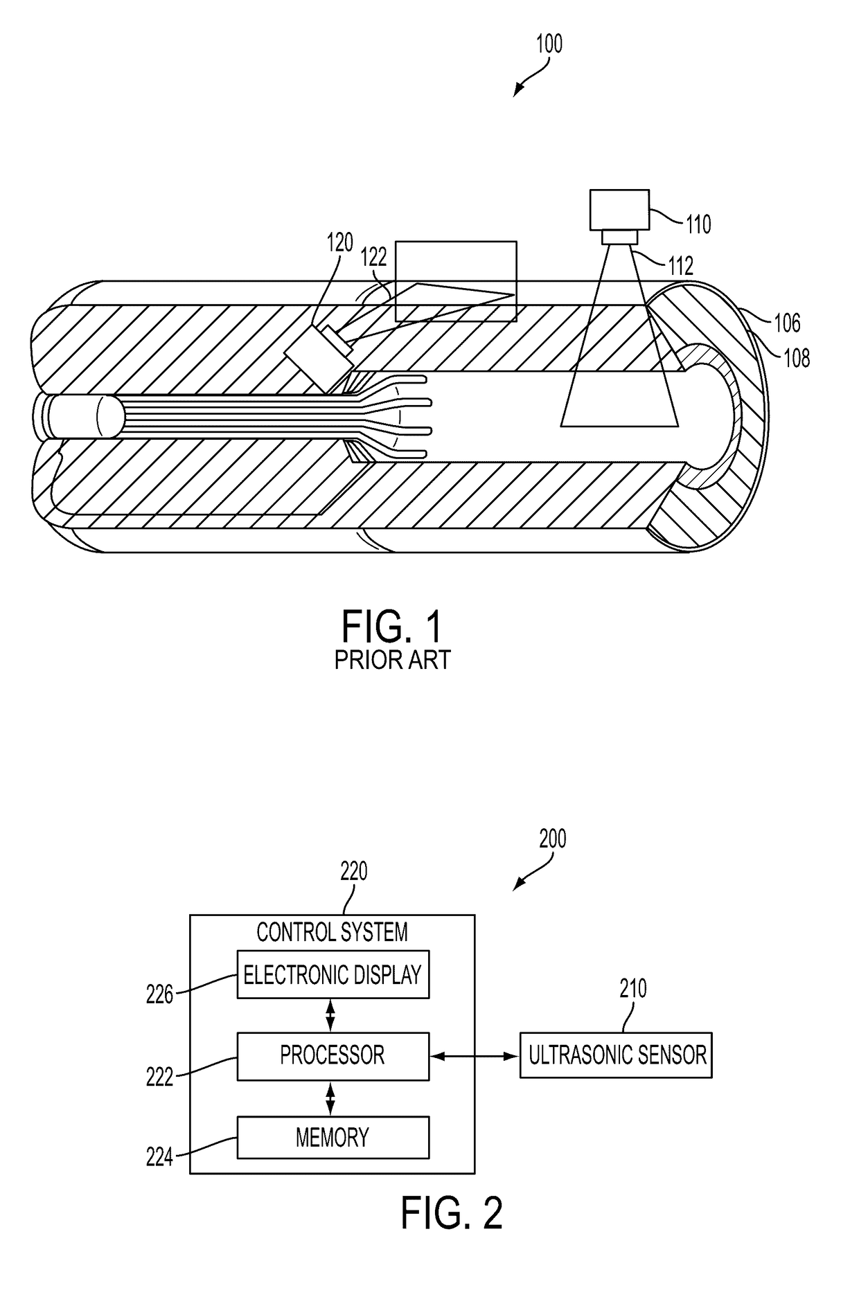
The conventional inspection methods, however, have not adequately provided the necessary depth to obtain accurate information any significant distance past the inside wall of case 106.
Therefore, defects in the insulation materials may be undetected.

Method used


Image

  • Methods and apparatus for detecting defects in an object of interest
  • Methods and apparatus for detecting defects in an object of interest
  • Methods and apparatus for detecting defects in an object of interest

Examples


Embodiment Construction

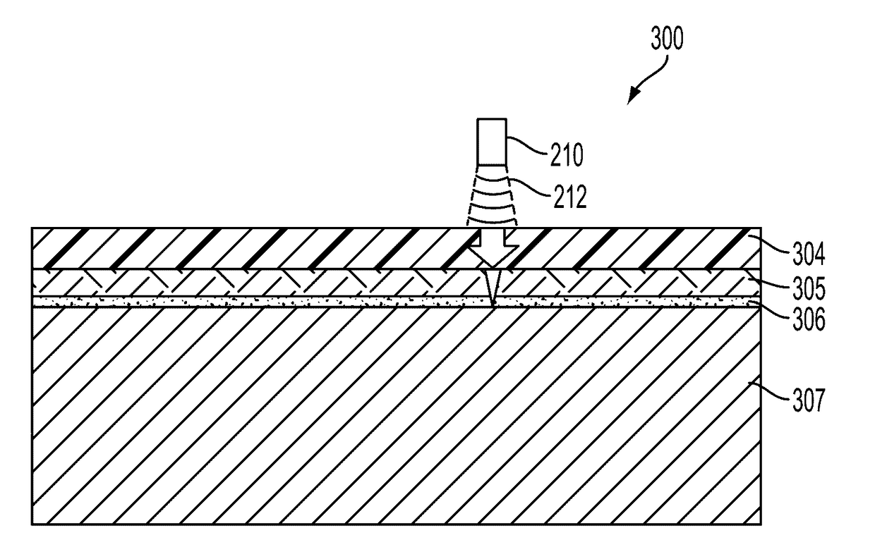
[0019]In the following description, reference is made to the accompanying drawings in which is shown, by way of illustration, specific embodiments of the present disclosure. Other embodiments may be utilized and changes may be made without departing from the scope of the disclosure. The following detailed description is not to be taken in a limiting sense, and the scope of the present invention is defined only by the appended claims.

[0020]Furthermore, specific implementations shown and described are only examples and should not be construed as the only way to implement or partition the present disclosure into functional elements unless specified otherwise herein. It will be readily apparent to one of ordinary skill in the art that the various embodiments of the present disclosure may be practiced by numerous other partitioning solutions.

[0021]In the following description, elements, circuits, and functions may be shown in block diagram form in order not to obscure the present disclos...


PUM

PropertyMeasurementUnit
frequencyaaaaaaaaaa
frequencyaaaaaaaaaa
frequencyaaaaaaaaaa

Abstract

A method for detecting defects in an object of interest comprises applying an ultrasonic signal including a tone burst having a predetermined frequency and number of cycles into an object of interest, receiving a return signal reflected from the object of interest, and processing the return signal to detect defects in at least one inner material. The object may have an outer material and the at least one inner material that have different acoustic impedances. An ultrasonic sensor system includes an ultrasonic sensor configured to generate an ultrasonic signal having a tone burst at a predetermined frequency corresponding to a resonant frequency of an outer material of an object of interest.

Description

STATEMENT REGARDING FEDERALLY SPONSORED RESEARCH OR DEVELOPMENT[0001]The U.S. Government has a paid-up license in this invention and the right in limited circumstances to require the patent owner to license others on reasonable terms as provided for by the terms of Contract No. NNM07AA75C awarded by NASA.TECHNICAL FIELD[0002]Embodiments of the present disclosure relate to detection of defects in an object using an ultrasonic sensor. In particular, embodiments relate to a method of detection of defects in materials located behind a higher acoustic impedance material, and to apparatus configured to implement the method.BACKGROUND[0003]Conventional nondestructive evaluation (NDE) techniques have been used in the Space Shuttle program to screen for defects (e.g., cracks, debond, voids, etc.) in the basic case, insulation, propellant assembly of the solid rocket motor. Uncertainty in the size, location, and orientation of defects may result in uncertainty in the analytical models (i.e., ...

Claims


Application Information

Patent Timeline
Patent Type & Authority Patents(United States)
IPC IPC(8): G01N29/11G01N29/22G01N29/34G01N29/44G01N29/265
CPCG01N29/11G01N29/225G01N29/265G01N29/343G01N29/348G01N29/4454
Inventor HARTMAN, JOHN K.PEARSON, LEE H
Owner NORTHROP GRUMMAN SYST CORP
Learn More