
Card holder

a card holder and card holder technology, applied in the field of wallets and card holders, can solve the problems of user discomfort, method of organizing cards that do not lend to the quick ejection or removal of individual cards, etc., and achieve the effect of improving the storage and retrieval of wallet-sized cards

Inactive Publication Date: 2017-03-07
VELENTZAS MICHAEL +1
View PDF9 Cites 1 Cited by
  • Summary
  • Abstract
  • Description
  • Claims
  • Application Information

AI Technical Summary

Benefits of technology

[0003]The invention relates to a card holder that slides open to permit access to a card stored therein. In some embodiments, the card holder slides open in multiple directions to provide access to various different cards stored therein. The aim of this invention is to improve on the storage and retrieval of wallet-sized cards.
[0004]The invention is made up of elements, features and components that are assembled to interlock in a manner that the components slide with respect to one another to expose cards stored inside. This sliding motion can happen in multiple directions to expose separate cards and allow for their easy retrieval.
[0005]The invention is made up of multiple layered components. A base component can hold a sliding component on a top side, a bottom side, or both sides thereof. These sliding components on either side of base component can also hold an additional sliding component on the side opposite the base component. Each sliding component is shaped to store a card therein. All of these components are preferably connected in a manner that allows for the components to slide with respect to one another. The Additionally, stoppers, resilient features and folded features in each component keep the card in place and prevent the sliding components from sliding beyond their necessary limits. The card holder functions such that one, several, or all, of its components can be slid open to reveal one, multiple or all of the cards at once. The components can, in some embodiments, all slide autonomously in a way that does not prohibit the sliding action of any of the other components.

Problems solved by technology

These methods for organizing cards do not lend to the quick ejection or removal of individual cards because they rely on precise and tedious finger work to extract individual cards.
Existing wallets and card holders that do employ ejection mechanisms often do not allow for selective removal of specific cards, and if they do, it is achieved through bulky designs that rely on buttons, springs, and thick sleeves—all elements that add thickness to the design and result in discomfort to the user.
These limitations have led to the need for a card-storage design that speeds up the process of card extraction without compromising on organization or adding to thickness.

Method used


Image

  • Card holder
  • Card holder
  • Card holder

Examples


Embodiment Construction

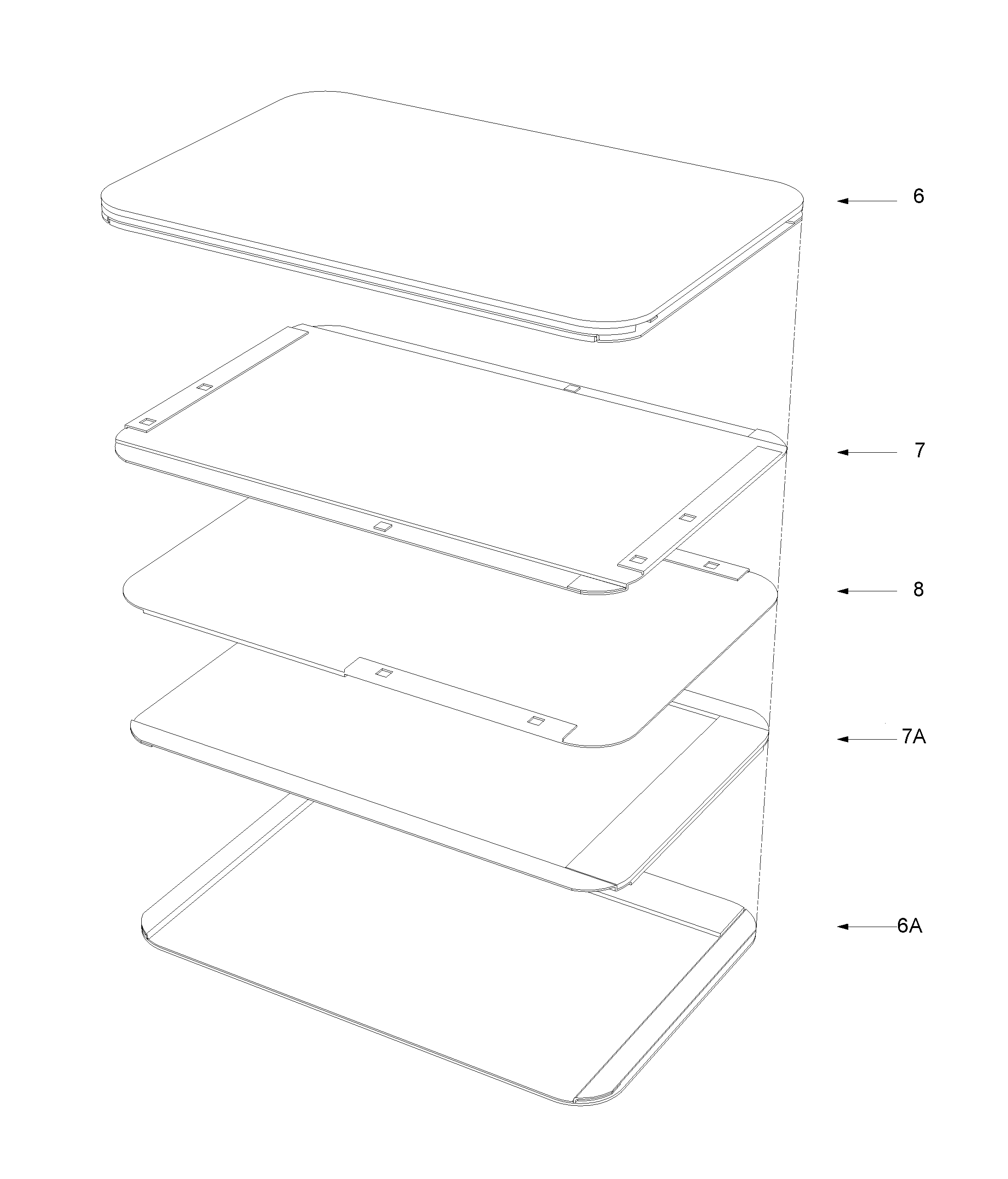
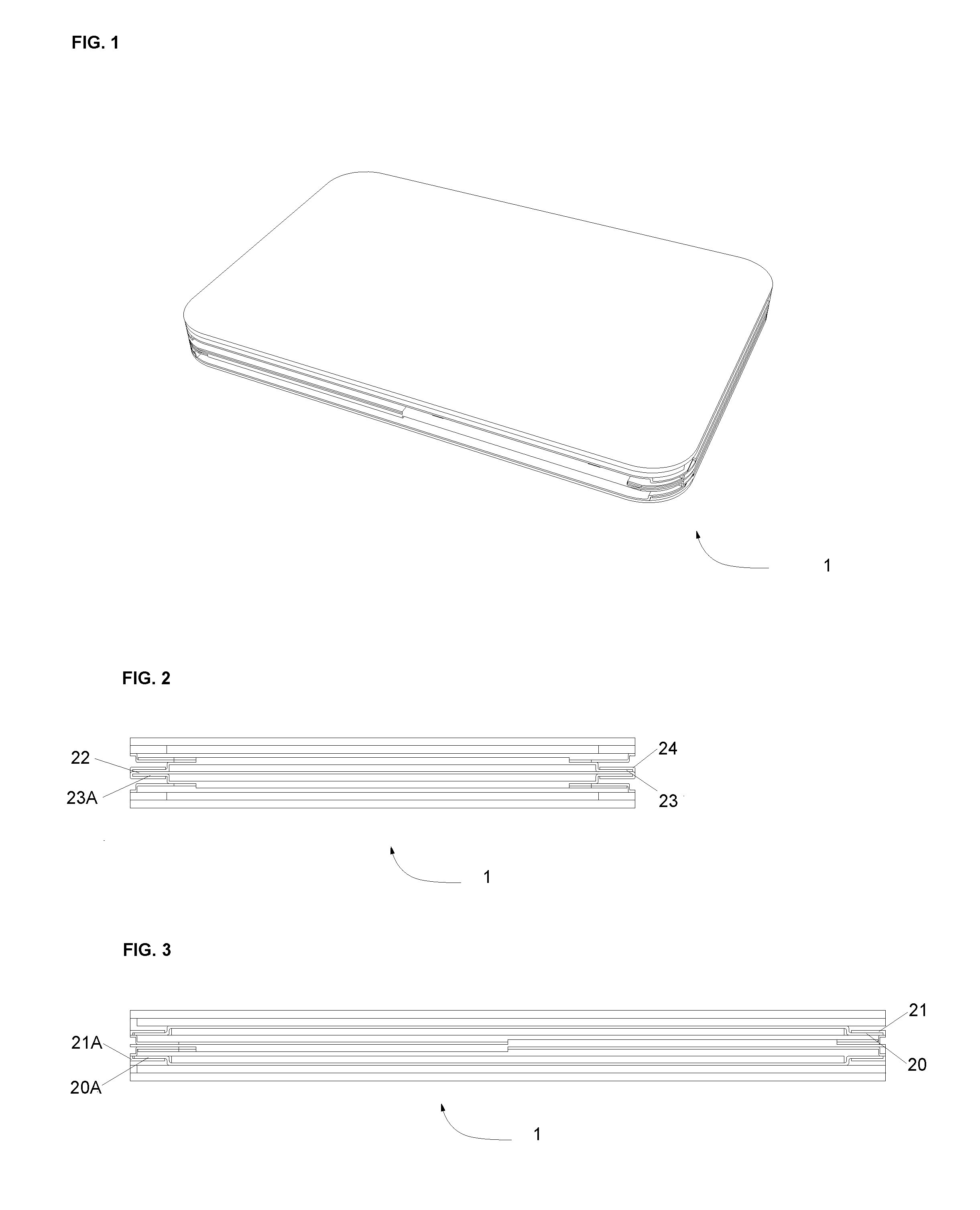
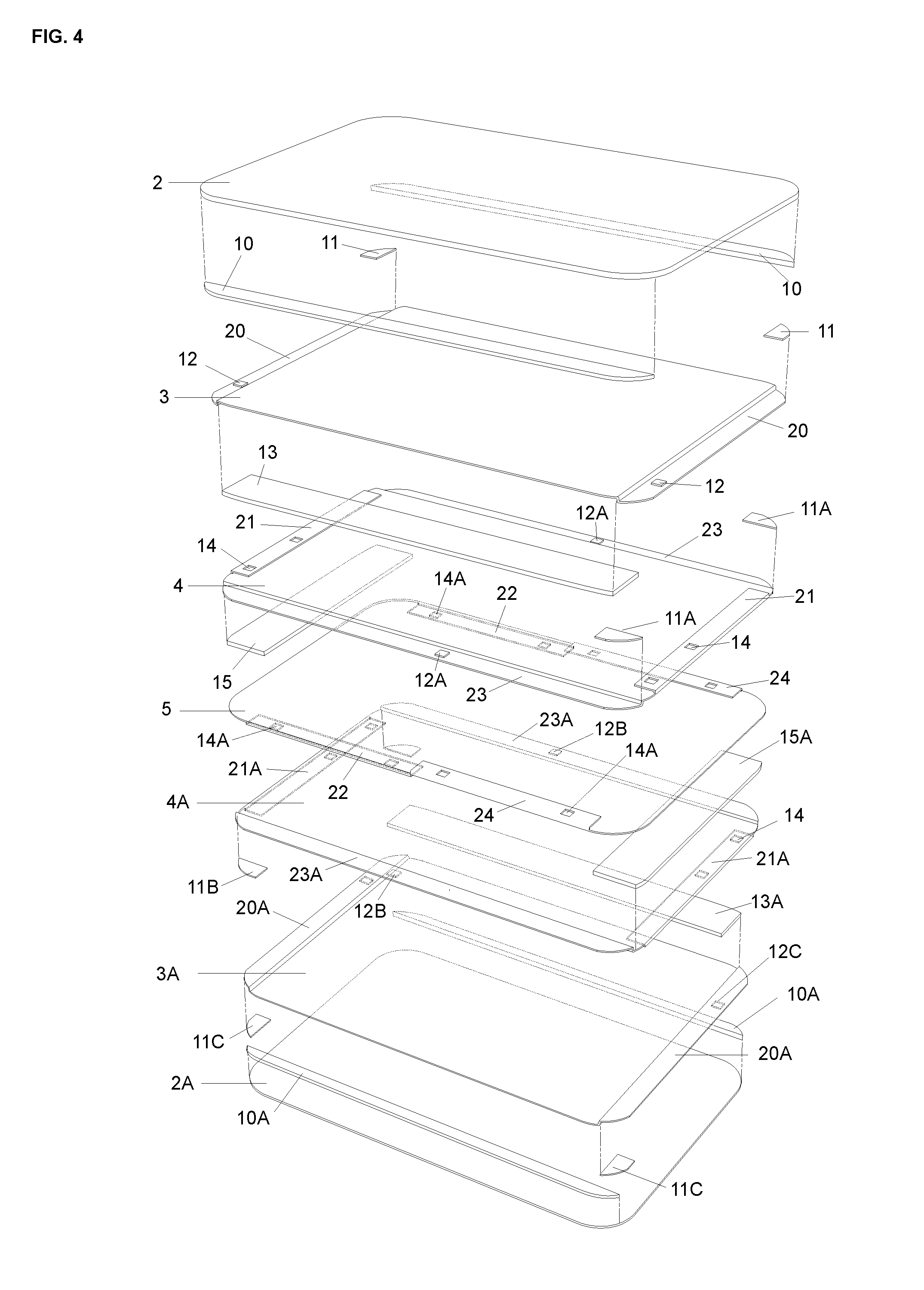
[0028]Embodiments of the card holder of the present invention are generally referred to throughout FIGS. 1-13 by the reference numeral 1. FIG. 5 shows one embodiment of the invention where card holder 1 has four sliding card storage compartments made from the assembly of components 6,7,8,7A, and 6A as well as two static card storage components in the outermost sliding components 6 / 6A. These components are, in turn, made up of the elements and features depicted in FIG. 4. FIGS. 2 and 3 show a front and side view of the card holder 1, respectively, to demonstrate the thickness of a card holder with four sliding components, as well as how the various features and elements come together.

[0029]The main components 6,7,8,7A, and 6A shown as distinct assemblies in FIG. 5 are shown in an exploded view in FIG. 4, where second top sliding component 6 is made up of elements 2, 3, 10, 11, 12, 13 and feature 20; first top sliding component 7 is made up of elements 4, 11A, 12A, 15 and features 21,...


PUM


Abstract

A card holder is provided, having at least one compartment that holds at least one card. When the compartment is slid open, at least one card is made accessible. There are preferably multiple compartments that make up the card holder, each compartment revealing a different card when slid to an open position.

Description

RELATED APPLICATIONS[0001]The present U.S. Utility Patent Application claims priority pursuant to 35 U.S.C. §119(e) to U.S. Provisional Application No. 61 / 931,597 entitled “Multi Directional Sliding Card Holder” filed Jan. 25, 2014, hereby incorporated by reference in its entirety and made part of the present U.S. Utility Application for all purposes.BACKGROUND OF THE INVENTION[0002]This application relates to wallets and card-holders, specifically ones that can store, organize, and eject wallet-sized cards (like driver's license ID's, credit cards, debit cards, and RFID passes). Wallets and card-holders typically store numerous cards in a stack, a single sleeve, stacked sleeves, or in a cascading set of sleeves. These methods for organizing cards do not lend to the quick ejection or removal of individual cards because they rely on precise and tedious finger work to extract individual cards. Existing wallets and card holders that do employ ejection mechanisms often do not allow for ...

Claims


Application Information

Patent Timeline
Patent Type & Authority Patents(United States)
IPC IPC(8): A45C11/18A45C1/06
CPCA45C11/182A45C1/06A45C2001/062A45C2001/065
Inventor VELENTZAS, MICHAELELIA, ANDREA
Owner VELENTZAS MICHAEL
Learn More