
Shoulder arthroplasty instrumentation

a shoulder arthroplasty and instrumentation technology, applied in the field of patient specific instruments, to achieve the effect of facilitating the placement of tools during surgery

Active Publication Date: 2017-02-28
NEW YORK SOC FOR THE RUPTURED & CRIPPLED MAINTAINING THE HOSPITAL FOR SPECIAL SURGERY
View PDF196 Cites 27 Cited by
  • Summary
  • Abstract
  • Description
  • Claims
  • Application Information

AI Technical Summary

Benefits of technology

The patient-specific instruments facilitate accurate placement and alignment of shoulder joint components, reducing revision rates and complications by ensuring optimal positioning and stability of the glenoid and humeral components during surgery.

Problems solved by technology

Glenoid component loosening and instability are important complications and may be caused by poor positioning of the component.

Method used


Image

  • Shoulder arthroplasty instrumentation
  • Shoulder arthroplasty instrumentation
  • Shoulder arthroplasty instrumentation

Examples


Embodiment Construction

Glenoid Component Instrument

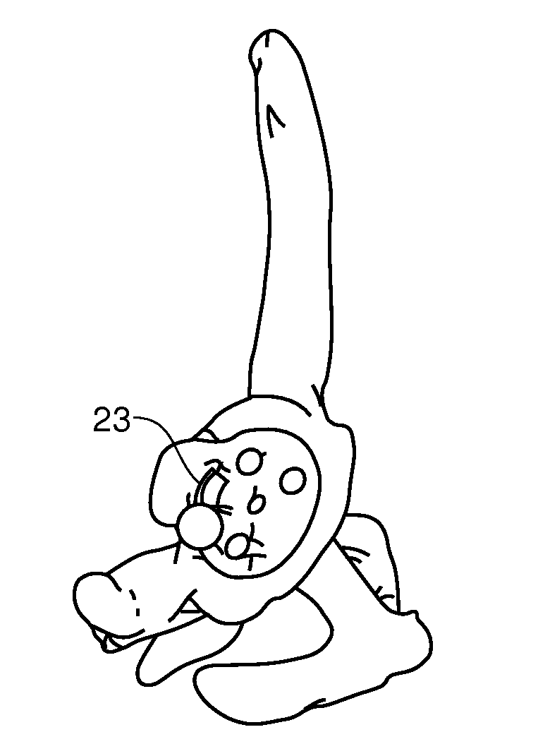
[0054]FIG. 1 through FIG. 5 should be considered together as they show the same glenoid component instrument 10 from several different perspectives. The glenoid component instrument 10 has a handle 12 attached to a generally oval or egg shaped disk shaped instrument body 14. The disk shaped body 14 has a patient specific conformal lower surface 16 that matches the surface of the articular portion of the glenoid joint. Adjacent the patient specific bottom surface 16 is a hook like feature that matches an off articular bony portion of the glenoid. This hook 18 is also patient specific and one or more such hooks may be formed depending on the patient anatomy. These features are placed on the sidewall 17 of the disk shaped instrument body. Also present are holes passing through the disk element of the instrument body from the lower surface to the upper surface. Holes useful for directing screws or the like are seen at reference numeral 20 and 22. A hole or sl...


PUM


Abstract

Patient specific shoulder component implant instruments are described for hemi and total, normal and reverse shoulder arthroplasty.

Description

CROSS-REFERENCE TO RELATED CASES[0001]The present case claims the benefit of and incorporates by reference both U.S. Provisional Patent Application 61 / 319,484, filed Mar. 31, 2010 entitled “Patient Specific Instruments” and U.S. Provisional Patent Application 61 / 325,435, filed Apr. 19, 2010 entitled “Total Shoulder Arthroplasty Instrumentation”.FIELD OF THE INVENTION[0002]The present invention relates to patient specific instrumentation to facilitate implantation of a total shoulder joint and to the process and technique for creating the instruments.BACKGROUND OF THE INVENTION[0003]Shoulder hemiarthroplasty is commonly used to treat patients with glenohumeral joint arthrosis. Total shoulder arthroplasty may be indicated for patients without a good articular surface on the glenoid at the time of surgery. For patients with glenohumeral joint arthrosis and an additional deficient rotator cuff, reverse total shoulder arthroplasty may be indicated. The 12%, 15%, and 22% revision rates, r...

Claims


Application Information

Patent Timeline
Patent Type & Authority Patents(United States)
IPC IPC(8): A61B17/56A61B17/15A61B17/17
CPCA61B17/15A61B17/1778A61B2017/568A61B2034/108
Inventor LO, DARRICKLIPMAN, JOSEPHPEARLE, ANDREW D.
Owner NEW YORK SOC FOR THE RUPTURED & CRIPPLED MAINTAINING THE HOSPITAL FOR SPECIAL SURGERY
Learn More