
Seismic isolation device and seismic isolation method

a seismic isolation and seismic isolation technology, applied in the direction of building components, building types, constructions, etc., can solve the problems of general seismic isolation apparatus composed of soft member and attenuation member not always effective against a large long-period, general seismic isolation apparatus composed of soft member and attenuation member may break its member,

Active Publication Date: 2017-02-21
KK TOSHIBA
View PDF16 Cites 1 Cited by
  • Summary
  • Abstract
  • Description
  • Claims
  • Application Information

AI Technical Summary

Benefits of technology

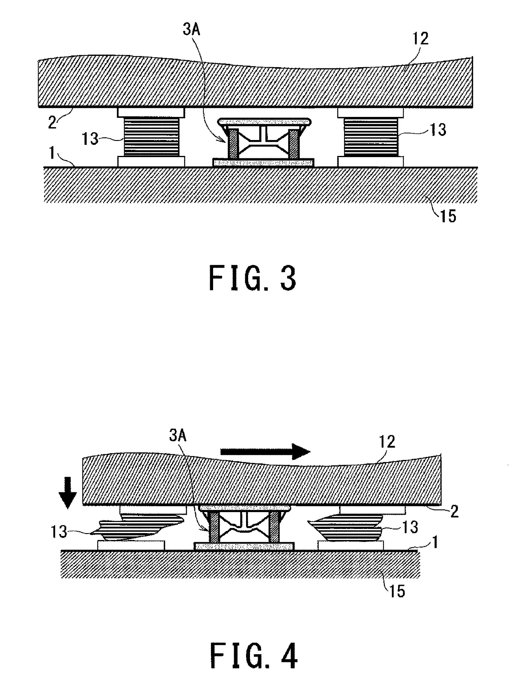
The present invention provides a seismic isolation apparatus and method that can absorb the impact force of a structure in case of a large long-period earthquake, reducing the possibility of damage to the structure. The seismic isolation method uses the apparatus and allows the inner and outer cylinders of the elasto-plastic damper to slide in axis direction, causing a plastic deformation of the elasto-plastic member inside the inner cylinder. This results in the effective absorption of seismic vibrations and the protection of the structure from damage.

Problems solved by technology

The general seismic isolation apparatus composed of the soft member and the attenuation member is not always effective against a large long-period displacement response even if the general seismic isolation apparatus is effective against a short-period displacement response.
The general seismic isolation apparatus has difficulty of designing seismic isolation for the large long-period displacement response.
That is, if a large long-period earthquake vibration beyond expectations is received, there is a possibility that a structure provided with a seismic isolation apparatus may break its member such as the laminated rubber due to exceeding a design allowable value.
The conventional method allowing the laminated rubber 100 to slide is not always effective against three-dimensional displacement in vertical and side-to-side directions even if the conventional method allowing the laminated rubber 100 to slide is effective against displacement in a side-to-side direction.
As a result, it may be impossible to absorb impact force generated by the structure 101.

Method used


Image

  • Seismic isolation device and seismic isolation method
  • Seismic isolation device and seismic isolation method
  • Seismic isolation device and seismic isolation method

Examples


first embodiment

(First Embodiment)

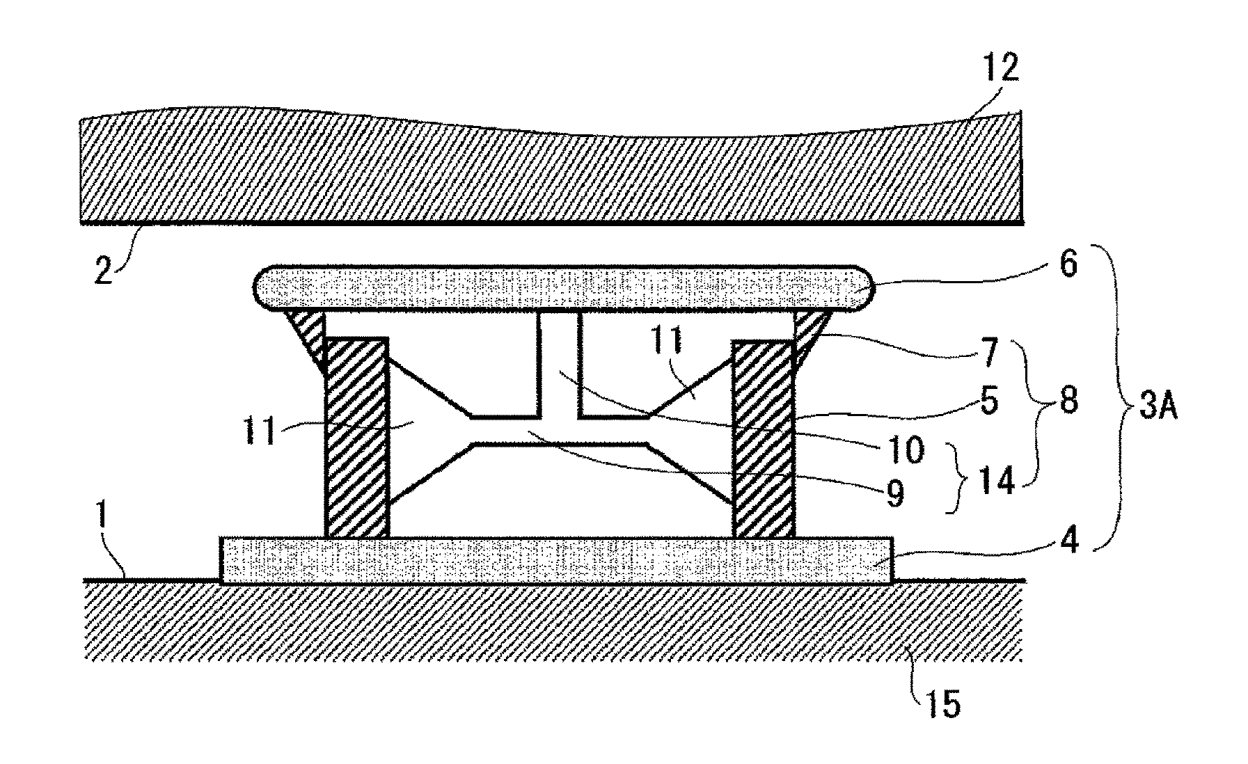
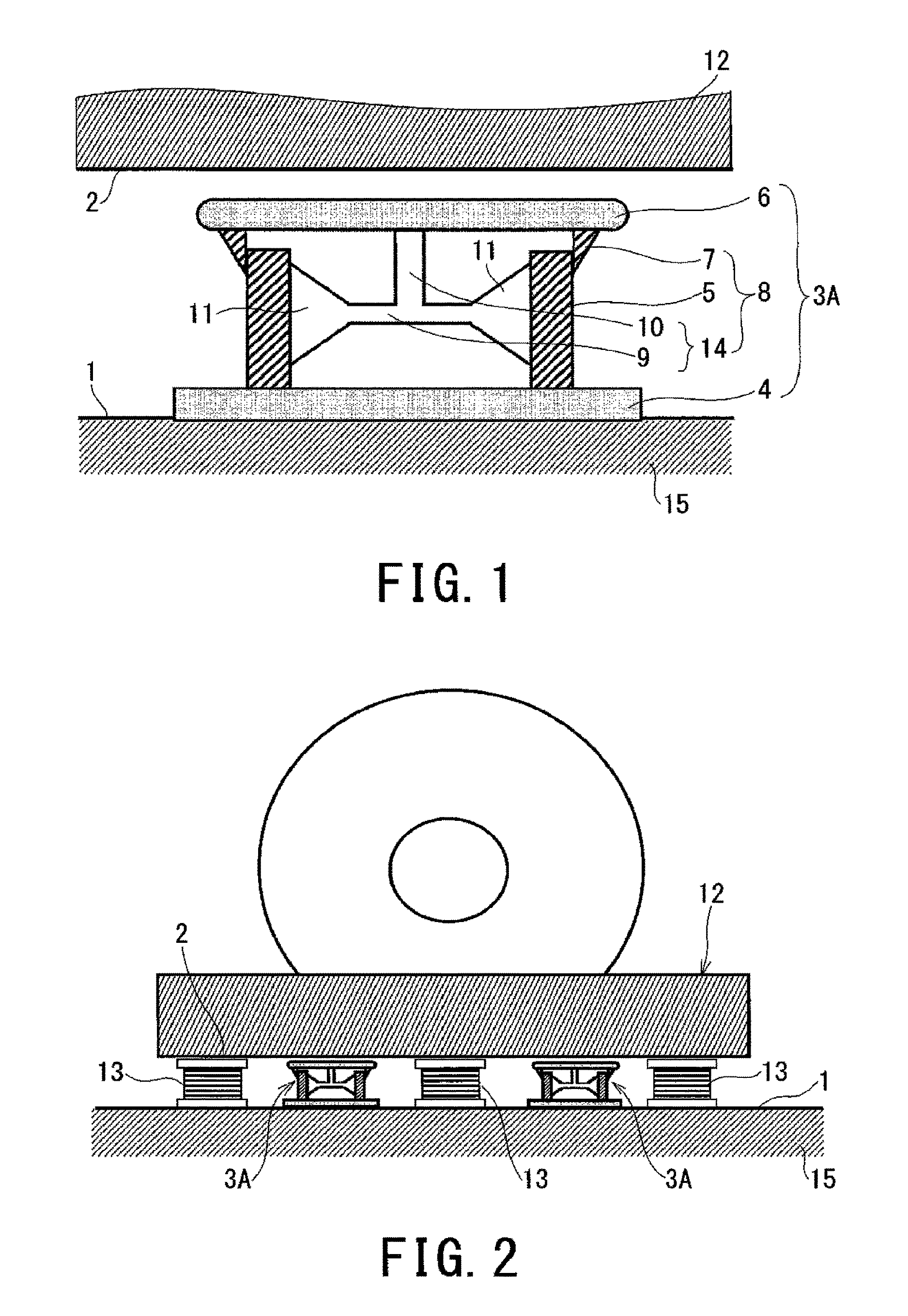
[0035]The seismic isolation apparatus and the seismic isolation method in accordance with a first embodiment, will be described.

[0036]FIG. 1 is a sectional view illustrating a seismic isolation apparatus (which will be referred to as “first seismic isolation apparatus”) 3A which is an example of a seismic isolation apparatus in accordance with first embodiment.

[0037]In accordance with FIG. 1, the first seismic isolation apparatus 3A includes a support plate 6, a base plate 4, and an elasto-plastic damper 8.

[0038]The support plate 6 is provided so as to face a lower surface 2 of a structure 12 at a predetermined interval. The base plate 4 is attached to a foundation floor 1 provided on a foundation 15. The support plate 6 is provided so as to secure a predetermined interval to the lower surface 2 of the structure 12, and so as not to be brought into contact with each other in a case where the first seismic isolation apparatus 3A is operated without being broken.

[003...

second embodiment

(Second Embodiment)

[0055]The seismic isolation apparatus and the seismic isolation method in accordance with a second embodiment, will be described.

[0056]FIG. 6 is a sectional view of a seismic isolation apparatus (which will be referred to as “second seismic isolation apparatus”) 3B which is an example of a seismic isolation apparatus in accordance with the second embodiment.

[0057]In accordance with FIG. 6, the second seismic isolation apparatus 3B has the same structure as that of the first seismic isolation apparatus 3A except that: the elasto-plastic member 14 is a rod-like body 17 formed of stainless steel or the like; the inner cylinder 5 and the outer cylinder 7 have the almost same height; a plurality of reinforcement plates 11 in the shape of triangle in cross section is provided along the inner cylinder 5 and the support plate 6, and along the outer cylinder 7 and the base plate 4; and the rod-like body 17 penetrates into the inner cylinder 5, and there is provided a conne...

third embodiment

(Third Embodiment)

[0060]The seismic isolation apparatus and the seismic isolation method in accordance with a third embodiment, will be described.

[0061]FIG. 7 is a sectional view of a seismic isolation apparatus (which will be referred to as “third seismic isolation apparatus”) 3C which is an example of a seismic isolation apparatus in accordance with the third embodiment.

[0062]In accordance with FIG. 7, the embodiment has the same structure as that of the second seismic isolation apparatus 3B except that a plurality of viscous dampers 20 each of which is composed of a cylinder 21 and a piston rod 22 is provided instead of the rod-like body 17 and the connection plate 16, constituting the elasto-plastic member 14 in the second embodiment.

[0063]The viscous damper 20 is set so that internal pressure of the cylinder 21 allows the piston rod 22 to be pressed on the lower surface of the support plate 6 and operation of the third seismic isolation apparatus 3A within a rated range does no...


PUM


Abstract

A seismic isolation apparatus is provided between a structure and a foundation floor, and the seismic isolation apparatus includes: a support plate that is provided so as to face the structure at a predetermined interval; a base plate that is fixed to the foundation floor; and an elasto-plastic damper that is provided between the support plate and the base plate to be fixed to the support plate and the base plate. The elasto-plastic damper includes an inner cylinder inside which an elasto-plastic member is provided and an outer cylinder, and the inner cylinder and the outer cylinder are configured to mutually slide in an axis direction thereof.

Description

CROSS-REFERENCE TO RELATED APPLICATION[0001]This application is based upon and claims the benefit of priority from Japanese Patent Application No. 2014-217146, filed on Oct. 24, 2014, the entire contents of which are incorporated herein by reference.BACKGROUND[0002]Field[0003]Embodiments of the present invention relate to a seismic isolation apparatus and a seismic isolation method.[0004]Description of the Related Art[0005]Seismic isolation devices have been introduced as earthquake countermeasures for structures, such as buildings, machines and equipment. The seismic isolation apparatus is generally composed of a soft member such as a laminated rubber, and an attenuation member such as an oil damper to prevent earthquake acceleration from being transmitted to a structure. The general seismic isolation apparatus composed of the soft member and the attenuation member is not always effective against a large long-period displacement response even if the general seismic isolation appara...

Claims


Application Information

Patent Timeline
Patent Type & Authority Patents(United States)
IPC IPC(8): E04B1/98E04H9/02
CPCE04H9/022E04H9/02E04H9/021E04H9/027E04H2009/026E04H9/0235
Inventor KATAYAMA, HIROSHIWATANABE, URARANAKAMURA, GAKUNIHIRA, YOSHITAKATANOUE, TETSUHARU
Owner KK TOSHIBA
Learn More