Collimator for radiotherapy apparatus

a collimator and radiotherapy technology, applied in the field of collimators, can solve the problems of increasing manufacturing complexity and little additional benefit in weight saving, and achieve the effect of reducing the size and therefore the weight of the collimator

Active Publication Date: 2017-02-21
ELEKTA AB
View PDF8 Cites 4 Cited by
  • Summary
  • Abstract
  • Description
  • Claims
  • Application Information

AI Technical Summary

Benefits of technology

[0009]The present invention provides a collimator for a radiotherapy apparatus, comprising a block of radiation-attenuating material for moving into and out of a beam of therapeutic radiation having a depth and a front face forming the leading edge of the block when, in use, it is moved into the beam and one, two or more main rear faces opposite the front face which main rear face(s) together substantially define(s) the trailing edge of the block when, in use, it is moved into the beam, the or each main rear face being substantially planar in the direction of the depth of the block and non-parallel to the front face. Such an arrangement enables the size and therefore weight of the collimator to be reduced as compared to conventional block collimators, as will be further described below.
[0010]There may be a single rear face, or there may be two rear faces which together form a concave V-shape in the block opposite the front face. The or each rear face is substantially planar and non-parallel to the front face. These arrangements are both simple and enable significant savings in block material and hence weight to be made; single rear face, or “wedge” embodiments, enable greater weight savings than similar implementations having two rear faces (or concave V-shaped embodiments), as will be explained below. Embodiments having three or more rear faces in a concave shape are technically feasible, but these are more complex to manufacture and provide little additional benefit in weight saving.
[0012]There may be two side faces leading from the front face to the rear face (where there is only one rear face); this provides a safety margin when movement of the block collimator and MLC leaves is initiated. The side faces may be substantially parallel.
[0013]The collimator may have a top and bottom face (as seen in the direction of the radiation beam which is collimated), and these faces may be planar; to the extent that they are planar these faces may be substantially parallel. Additionally or alternatively, these faces may be shaped as described in our EP2153448A1, so as to provide additional weight saving; in particular the edge of the collimator block at its front face (the front edge) may be of greater thickness than at least one region behind the front edge (i.e. towards the rear face(s), between the leading and trailing edges of the block.

Problems solved by technology

Embodiments having three or more rear faces in a concave shape are technically feasible, but these are more complex to manufacture and provide little additional benefit in weight saving.

Method used


Image

  • Collimator for radiotherapy apparatus
  • Collimator for radiotherapy apparatus
  • Collimator for radiotherapy apparatus

Examples


Embodiment Construction

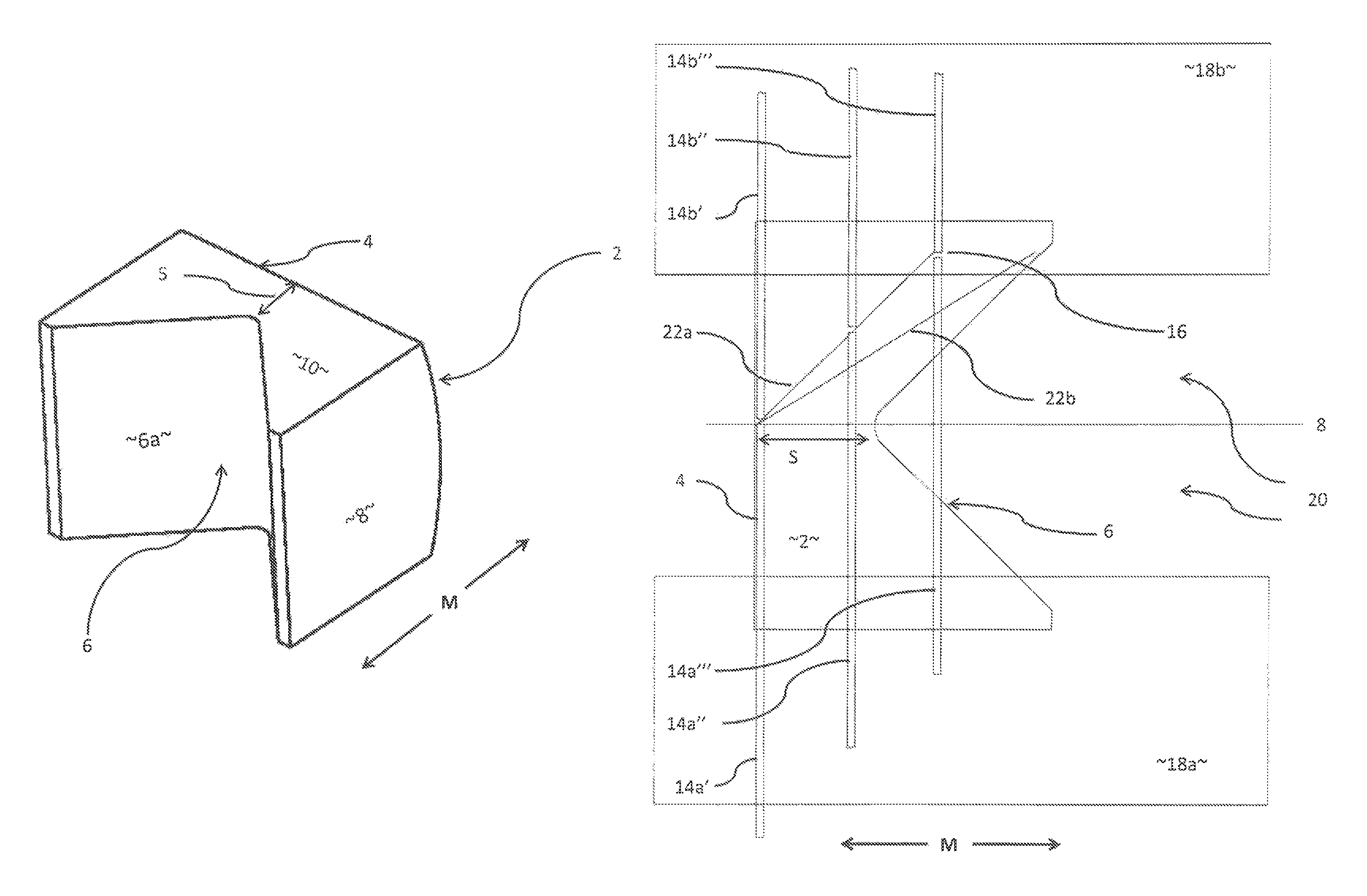
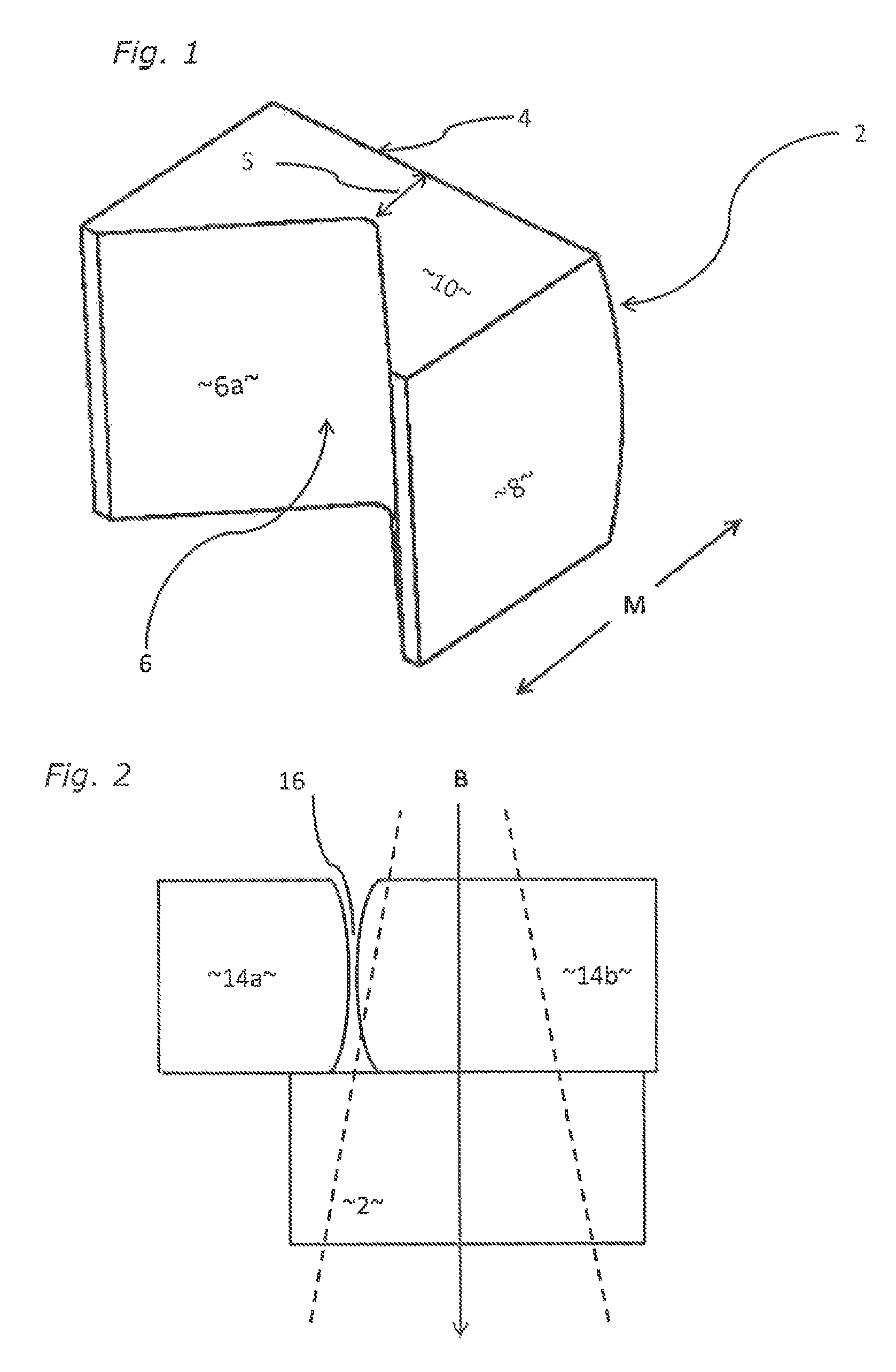
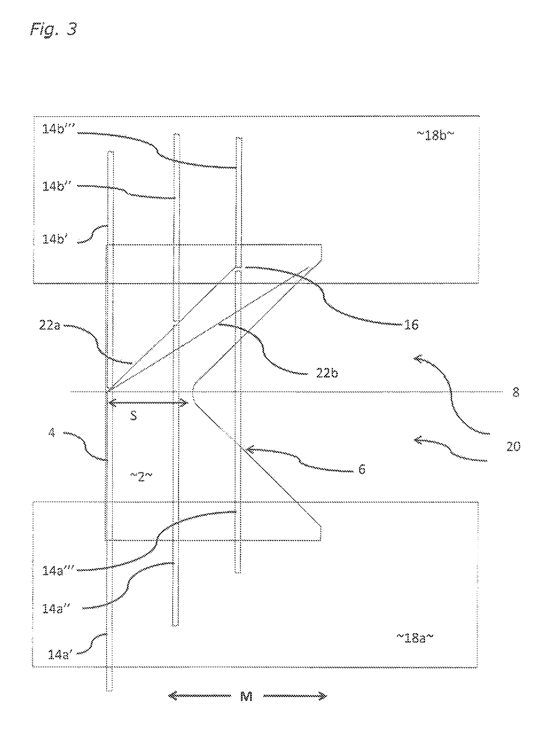
[0021]The present invention is predicated upon the movement of the leaves of an MLC. In one particular arrangement, where the MLC leaves are capable of travelling across the entire width of the aperture formed by the primary collimator edge, we have recognised that it is not necessary to have a collimator block which extends across the aperture for the entirety of its length (i.e. in the direction parallel to the direction of movement of the collimator block—“the movement direction”), because the main source of radiation leakage (the attenuation of which is a main objective of the collimator block) is not between the sides of the leaves but rather through the “gap” between opposing leaf tips. When the leaf tips are outside of the beam of radiation (i.e. extended fully across the aperture, so that the “gap” between the leaf tips is within the penumbra of the primary collimator edge and hence shielded from the radiation source) there is no radiation leakage as such, and the collimator...


PUM


Abstract

A collimator for a radiotherapy apparatus, comprising a block of radiation-attenuating material having a front face forming the leading edge of the block and at least one main rear face defining the trailing edge of the block, in which the or each rear face is substantially planar in the direction of the depth of the block and non-parallel to the front face. The collimator may form part of a radiotherapy apparatus, and methods of operation of such apparatus are described.

Description

CROSS REFERENCE TO RELATED APPLICATION[0001]The present application claims the benefits of priority to GB 1317016.2, filed on Sep. 25, 2013, and GB 1411005.0, filed on Jun. 20, 2014. The entire content of each of the above referenced applications is incorporated herein by reference.FIELD OF THE INVENTION[0002]The present invention relates to a collimator, particularly but not exclusively to a collimator for radiotherapy apparatus.BACKGROUND ART[0003]Radiotherapy is a form of treatment for tumours and other lesions which involves directing a beam of ionising radiation toward the lesion. The radiation harms the tumour tissue and causes its reduction or elimination. However, the radiation is also harmful to healthy tissue around the lesion; although healthy tissue is slightly less susceptible to the effects of ionising radiation, measures are taken to limit the exposure of healthy tissue to the extent possible.[0004]One such measure is to direct the beam toward the lesion from a number...

Claims


Application Information

Patent Timeline
Patent Type & Authority Patents(United States)
IPC IPC(8): A61N5/10G21K1/10G21K1/04
CPCA61N5/1045A61N5/1077G21K1/10G21K1/046G21K1/025
Inventor WILLCUT, VIRGILBROAD, MARTINROBERTS, DAVID ANTHONY
Owner ELEKTA AB
Why Eureka
Try Eureka