Generator for producing electric power

a generator and electric power technology, applied in the direction of mechanical energy handling, machines/engines, mechanical equipment, etc., can solve the problems of shortening the life of the converter, reducing the efficiency of the converter, and increasing the requirements for converter cooling, so as to improve the controllability of the generator unit, the effect of increasing the flux and increasing the controllable curren

Active Publication Date: 2017-02-14
SIEMENS GAMESA RENEWABLE ENERGY AS
View PDF7 Cites 4 Cited by
  • Summary
  • Abstract
  • Description
  • Claims
  • Application Information

AI Technical Summary

Benefits of technology

[0010]Embodiments of the invention are based on the idea that the first (or main) set of windings and the first (or main) converter are mainly dedicated to power generation while the second (or auxiliary) set of windings and the second (or auxiliary) converter are mainly dedicated to generation of control voltages and / or control currents in the second set of windings in order to perform various control functions on the generator unit. Thereby, the first converter can be optimized with regard to power production, while the second converter can be optimized with regard to control functions. Since the first converter does not need to be involved in the control functions, the first converter can be designed in a simple manner with cheap components optimized for handling high power levels. On the other hand, as the performance of the control functions involves handling of significantly less power in comparison to the first converter, the second converter can be designed to perform the control functions without having to account for the above described considerations with regard to high power levels. This has the further advantage that the currents in the second set of windings will be significantly lower than the currents in the first set of windings. Thus, the wires used for the second windings may have a significantly lower current rating, i.e. no more than a third of the current rating of the wires used for the first set of windings, and may accordingly be added to the stator without incurring significant costs and without taking up a significant amount of space.
[0035]This embodiment is particularly advantageous in case the first converter is a diode-based rectifier and the second converter is a full-bridge active converter operating in PWM-mode. In this case, cheaper standard components can be used in the second converter and at the same time higher controllable currents can be achieved in the second set of windings, which improves the controllability of the generator unit (higher flux). At the same time, the voltage level on the first converter (diode rectifier) can be kept relatively high in order to reduce the current rating and the electrical losses.

Problems solved by technology

As each switching causes additional power losses in the power components (and thus heat), a higher switching frequency will not only cause reduced efficiency and increased requirements for converter cooling, but also more importantly result in a shorter lifetime for the converter.
The latter is particularly undesirable for offshore wind power applications.
Given the existing power component techniques, it is difficult to handle the required power level for wind power generation with a single power unit.
Nevertheless, some compromises are still placed to allow less ideal switching, and more modules have to be used to create the needed current / power margins.
However, an increased number of components means higher cost and less reliability on the system level.
The technical challenges to the conventional converter system are becoming severer as wind power generation is heading towards even higher voltages and larger power levels.
However, the generator stator currents cannot be controlled directly and independently using a diode rectifier.
Furthermore, known torque ripple methods using a boost converter in the DC link suffer from limited controllability and increased latency due to the diode rectifier.
Furthermore, the conduction losses will also be low due to the relatively low voltage drop in the diodes.

Method used


Image

  • Generator for producing electric power
  • Generator for producing electric power
  • Generator for producing electric power

Examples


Embodiment Construction

[0056]The illustration in the drawing is schematic. It is noted that in different figures, similar or identical elements are provided with the same reference numerals or with reference numerals which differ only within the first digit.

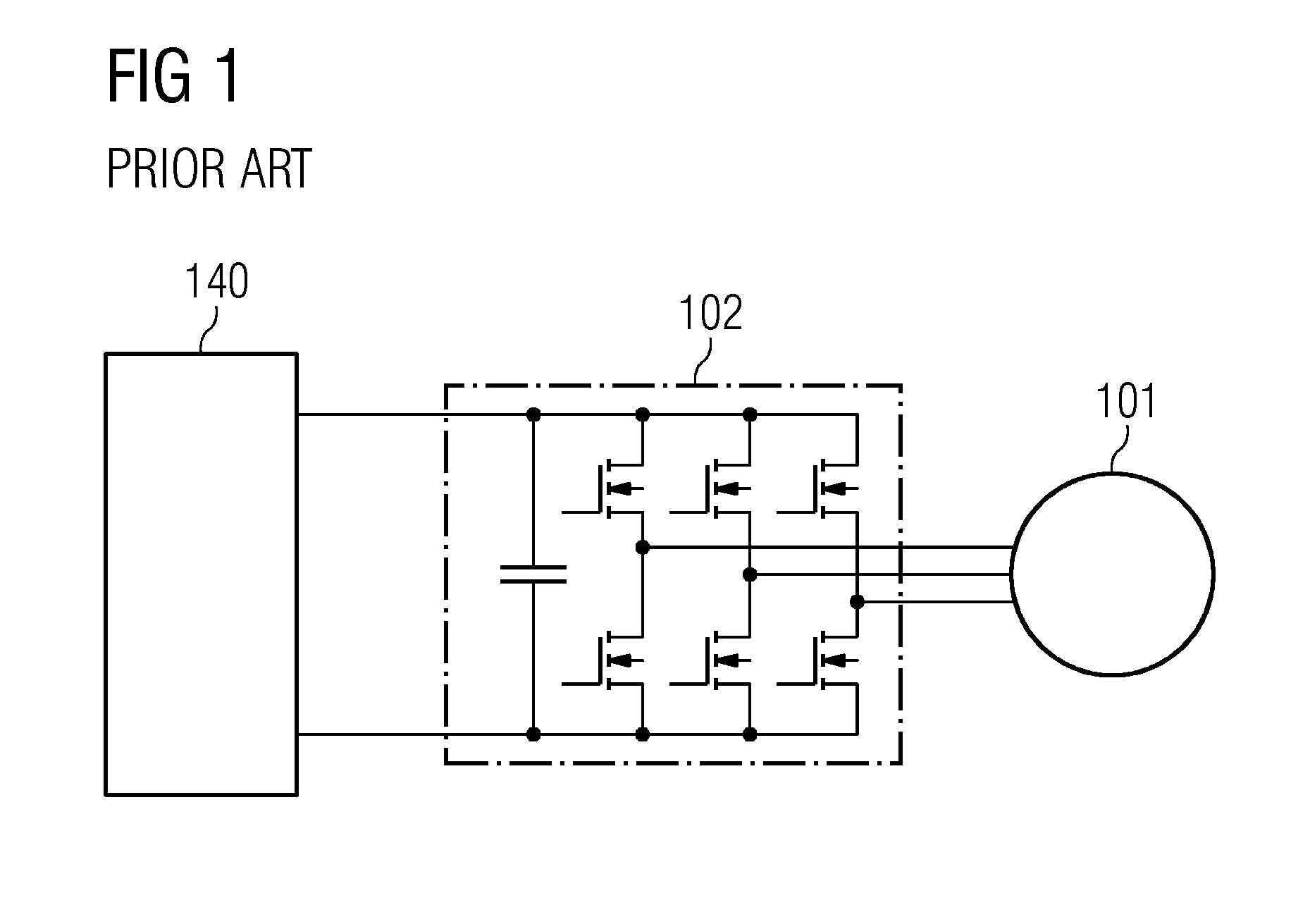
[0057]FIG. 1 shows a generator according to the prior art. More specifically, FIG. 1 shows a generator comprising a generator unit 101, such as a wind turbine generator, and a voltage source converter system 102 for converting 3 phases of alternating voltage output by the generator unit 101 into an output DC voltage. The output DC voltage is fed to grid 140. As discussed in the introduction of the present application, the voltage source converter system 102 operates in PWM mode in order to both provide the output DC voltage and to perform various control functions on the generator unit, such as flux control (Id currents) and injection of harmonic currents for reducing torque ripple etc.

[0058]FIG. 2 shows a generator according to an embodiment of the pr...


PUM


Abstract

A generator for producing electric power, the generator including a generator unit including a stator) and a rotatably supported rotor, wherein the stator includes a first set of windings and a second set of windings, and the rotor is adapted to induce electrical voltage in the first set of windings and in the second set of windings when the rotor is rotated relative to the stator, the generator further includes a first converter coupled to the first set of windings, the first converter being adapted to convert alternating voltage in the first set of windings into an output DC voltage, a DC output coupled to the first converter to receive the output DC voltage, and a second converter coupled to the second set of windings and to the DC output, the second converter being adapted to generate control voltages and / or control currents in the second set of windings, is provided.

Description

CROSS-REFERENCE TO RELATED APPLICATIONS[0001]This application claims priority to European Application No. 14166394.8, having a filing date of Apr. 29, 2014, the entire contents of which are hereby incorporated by reference.FIELD OF TECHNOLOGY[0002]The following relates to the field of generators for producing electric power, in particular, to generators for producing an output DC voltage based on alternating currents induced by rotation, e.g. of a wind turbine. The following further relates to a system for generating electric power and to a method of producing electric power.BACKGROUND[0003]In electric power generation, such as wind power generation, one of the established configurations is to use a full power back-to-back converter system. In such systems, the generator, e.g. wind turbine, is controlled by a voltage source converter to deliver power to a DC link, and another voltage source converter connected to this DC link is controlled to feed the power to the grid.[0004]In conv...

Claims


Application Information

Patent Timeline
Patent Type & Authority Patents(United States)
IPC IPC(8): H02J3/00H02P25/22H02J3/36H02P9/02F03D9/00H02P9/14H02J3/38
CPCH02J3/36F03D9/257H02P9/02H02P9/14H02P21/24H02P25/22H02J3/386Y02E10/725Y02E10/76H02K7/183Y02E10/72
Inventor ANDRESEN, BJORNPETERSEN, JESPER ELLIOTTHOMAS, ARWYNWU, ZHAN-YUANXIA, ZHEN PING
Owner SIEMENS GAMESA RENEWABLE ENERGY AS
Why Eureka
Try Eureka