[0007]With the aid of the present invention, a deceleration potential of the at least one electric motor may be better used. The present invention may also be described as an expansion of the limited regenerative deceleration potential by a non-compensated or blended regenerative deceleration component. With the aid of this additional non-compensated or blended deceleration component, it is possible to improve a regenerative efficiency of a braking system. As explained in greater detail below, this improvement is possible with no resulting changes to the deceleration behavior of the braking system being noticeable to the driver. Similarly, the driver senses no changes or virtually no changes when actuating a brake actuating element such as, for example, a brake pedal, but instead experiences a standard brake actuating sensation or pedal feel.
[0009]The additional exertion of the additional braking torque with the aid of the at least one electric motor of the vehicle may increase the recuperation efficiency of the motor. In particular, a more rapid chargeability of a vehicle battery may be ensured in this way. The present invention therefore assists in reducing fuel consumption and / or the pollutant emissions of the vehicle.
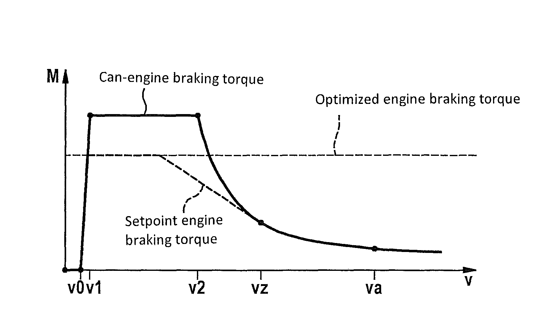
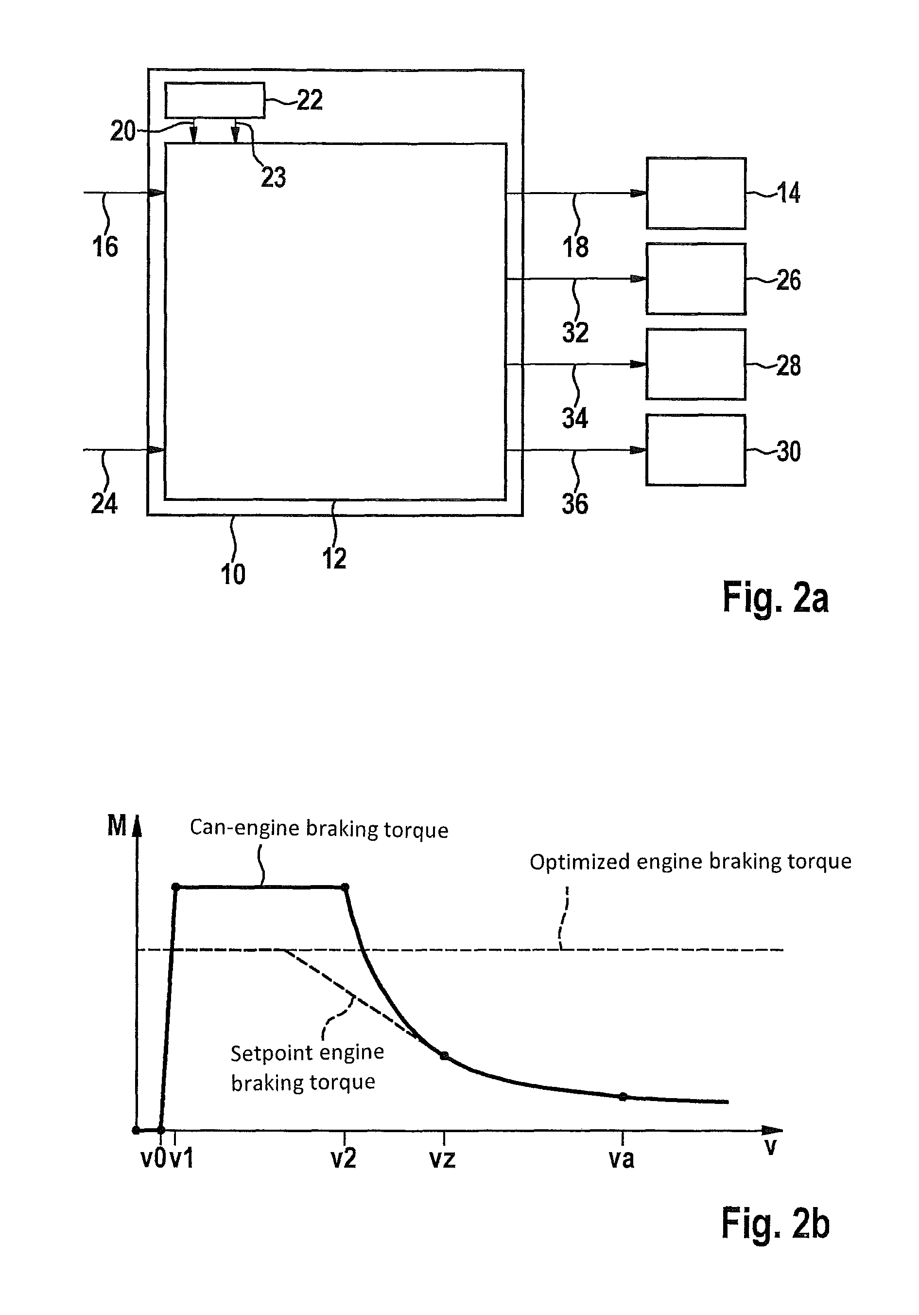
[0011]In one advantageous specific embodiment, the engine control device is also configured to define the at least one setpoint engine braking torque variable taking into additional consideration at least one provided or ascertained can-engine braking torque variable relative to the maximum can-engine braking torque impartable with the aid of the at least one electric motor. Thus, when controlling the at least one electric motor, a reduction of the maximum impartable can-engine braking torque, for example, due to a fully charged vehicle battery and / or a reduction of the vehicle speed below a minimum speed in generator mode, may also be taken into consideration. The setpoint engine braking torque may also be increased if the maximum impartable can-engine braking torque increases, for example, due to the instantaneous speed of the vehicle. The approaches described herein contribute to a more effective operation of the at least one electric motor used in generator mode, and to an increase in the recuperation efficiency of the regenerative braking system.
[0012]Moreover, the engine control device or another control device may be configured to define the at least one actual friction braking torque variable or at least one setpoint friction braking torque variable, taking into consideration at least the setpoint overall braking torque variable, and to control at least one component of the braking system with the aid of one additional control signal in such a way that the at least one actual friction braking torque may be imparted with the aid of the at least one additional friction brake according to the at least one actual friction braking torque variable or the at least one setpoint friction braking torque variable. This multifunctionality of the control device also allows the actual friction braking torque exerted with the aid of the at least one additional friction brake to be advantageously adapted to the requested setpoint overall braking torque and / or to the maximum impartable can-engine braking torque. This ensures an improved braking comfort. In addition, a savings on control electronics may also be achieved due to the multifunctionality of the control device.
[0014]In one advantageous specific embodiment, the engine control device or the additional control device is configured to control, with the aid of the at least one additional control signal, at least one shut-off valve, via which a brake circuit is connected to a brake master cylinder of the hydraulic braking system, at least one pump of the brake circuit, which is connected on the intake side to a brake fluid reservoir and on the discharge side to at least one wheel brake cylinder of the brake circuit as the at least one additional friction brake, and / or at least one continuously adjustable valve of the brake circuit, via which the at least one wheel brake cylinder is connected to the brake fluid reservoir, as the at least one hydraulic component. In this case, the control device may be used to operate a braking system, which includes a brake circuit, which may be decoupled from the brake master cylinder, or which may be decoupled at an axle. Thus, the decoupleable brake circuit may be used for blending at least one part of an actual engine braking torque exerted with the aid of the at least one electric motor, with no feedback effects occurring on the brake actuation element such as, for example, pedal feedback effects. Thus, the control device may be employed with a braking system, which is a cost-efficient alternative to a wheel brake actuator or brake-by-wire braking system, which is fully decoupled from a brake actuating element. At the same time, such a partially decoupleable braking system offers improved pedal comfort for the driver as opposed to a braking system in which the driver must carry out the deceleration regulating function himself.
[0016]In another advantageous specific embodiment, the engine control device is configured to define the at least one setpoint engine braking torque variable so that, given a constant setpoint overall braking torque variable or a constant setpoint overall braking torque, the setpoint engine braking torque may increase at most with a predefined limit increase gradient of not more than 0.3 m / s3. The setpoint engine braking torque in this case (for example, when the position of the brake actuation device remains unchanged) may increase at most with a predefined limit increase gradient of not more than 0.2 m / s3, or even not more than 0.1 m / s3. The gradient limitation described causes a pleasant brake actuation feeling or pedal feel for the driver when the setpoint engine braking torque is increased. This may also be described as the gradient of the setpoint engine braking torque corresponding consistently to a maximum of a fixed value (for example, 0.1 m / s3) and a change of the driver braking intention.
