Ball joint pinion for a drawer slide assembly

a technology of ball joint pinion and drawer slide assembly, which is applied in the field of applications, can solve the problems of improper seal of the drawer in the closed position, easy misalignment of the pull-out drawer between the sides, and difficulty in further movement of the drawer

Active Publication Date: 2017-02-14
HAIER US APPLIANCE SOLUTIONS INC
View PDF7 Cites 9 Cited by
  • Summary
  • Abstract
  • Description
  • Claims
  • Application Information

AI Technical Summary

Benefits of technology

The present invention provides a drawer assembly for a consumer appliance that has an anti-racking system to prevent misalignment of the drawer. Specifically, the invention provides a drawer slide assembly with a pinion gear and connecting rod assembly that reduces racking of the appliance drawer during movement in and out of an appliance chamber. The appliance drawer is attached to the appliance chamber using a ball and joint pinion gear configuration that adds another degree of freedom to the anti-racking system to reduce stress on the pinion gear. This improvement helps to improve the performance and lifetime of the drawer assembly.

Problems solved by technology

Due to their substantial width, depth, and weight, the pull-out drawers are susceptible to misalignment between the sides when moving the drawer into and out of the appliance compartment, particularly if the door is grasped off-center and the pulling / closing force is applied non-parallel to the slide structure.
This misalignment may lead to binding or “racking” of the drawer, which may make further movement of the drawer difficult and may also lead to an improper seal of the drawer in the closed position.
Although the pinion gear and connecting rod assembly discussed above is beneficial in minimizing the occurrence of racking, the pinion gears may be subjected to substantial forces and stresses during operation.
For example, axial, transverse, and torsional forces are imparted on the pinion gears during operation, which may lead to pinion gear failure.
Particularly when the drawer has any horizontal flexibility, torsional forces may place excessive stress on the pinion gears and cause premature failure.

Method used


Image

  • Ball joint pinion for a drawer slide assembly
  • Ball joint pinion for a drawer slide assembly
  • Ball joint pinion for a drawer slide assembly

Examples


Embodiment Construction

[0031]Reference now will be made in detail to embodiments of the invention, one or more examples of which are illustrated in the drawings. Each example is provided by way of explanation of the invention, not limitation of the invention. In fact, it will be apparent to those skilled in the art that various modifications and variations can be made in the present invention without departing from the scope or spirit of the invention. For instance, features illustrated or described as part of one embodiment can be used with another embodiment to yield a still further embodiment. Thus, it is intended that the present invention covers such modifications and variations as come within the scope of the appended claims and their equivalents.

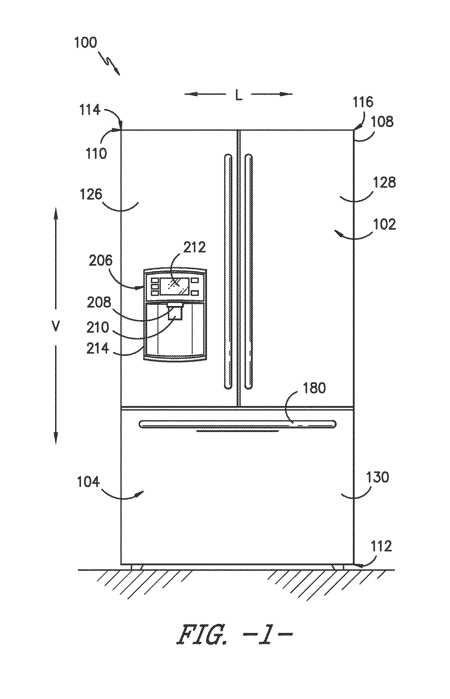
[0032]FIG. 1 provides a front, elevation view of a refrigerator appliance 100 according to an exemplary embodiment of the present subject matter with refrigerator doors 102 and freezer drawer 104 of the refrigerator appliance 100 shown in a closed position....


PUM


Abstract

A drawer assembly for a consumer appliance is provided. The drawer assembly includes an anti-racking system for minimizing misalignment of an appliance drawer. More particularly, the present subject matter provides a drawer slide assembly for a drawer having some horizontal flexibility. The drawer slide assembly may have a pinion gear and connecting rod assembly that minimizes racking of the appliance drawer as it is moved into and out an appliance chamber. The appliance drawer may be attached to the appliance chamber by a ball and joint pinion gear configuration that adds another degree of freedom to the anti-racking system in order to reduce stress on the pinion gear. By adding an additional degree of freedom to the pinion gear and reducing the imposed stresses applied to the pinion gear, the performance and lifetime of the drawer assembly may be improved.

Description

FIELD OF THE INVENTION[0001]The present subject matter relates generally to appliances, such as refrigerator appliances, and drawer assemblies for the same.BACKGROUND OF THE INVENTION[0002]Various types of consumer appliances are designed with pull-out compartment drawers. For example, a number of popular refrigerator styles have freezer compartments with one or more pull-out drawers that span the width of the appliance and include storage baskets or bins. The conventional pull-out drawers typically include side brackets that are mounted to slides of a slide mechanism that, in turn, has a base member mounted to the compartment liner.[0003]Due to their substantial width, depth, and weight, the pull-out drawers are susceptible to misalignment between the sides when moving the drawer into and out of the appliance compartment, particularly if the door is grasped off-center and the pulling / closing force is applied non-parallel to the slide structure. This misalignment may lead to binding...

Claims


Application Information

Patent Timeline
IPC IPC(8): F25D25/00F25D25/02
CPCA47B88/04F25D25/025A47B2210/0078A47B2210/175A47B88/45
Inventor JANSEN, KATHERINE MICHELLE
Owner HAIER US APPLIANCE SOLUTIONS INC
Why Eureka
Try Eureka