
System for delivering at least one shifted analogical output signal

a technology of analogical output and output signal, which is applied in the direction of instruments, mechanical devices, devices using electric/magnetic means, etc., can solve the problems of difficult and costly methods, difficult and expensive methods to implement, and the use of sensor-bearing units without a lot of experience and knowledge on motor control strategies. achieve the effect of simple system

Inactive Publication Date: 2017-02-07
AB SKF
View PDF8 Cites 0 Cited by
  • Summary
  • Abstract
  • Description
  • Claims
  • Application Information

AI Technical Summary

Benefits of technology

[0011]The aim of the invention is to provide simple system and method for shifting at least one of the analogical output signals of a sensor device.
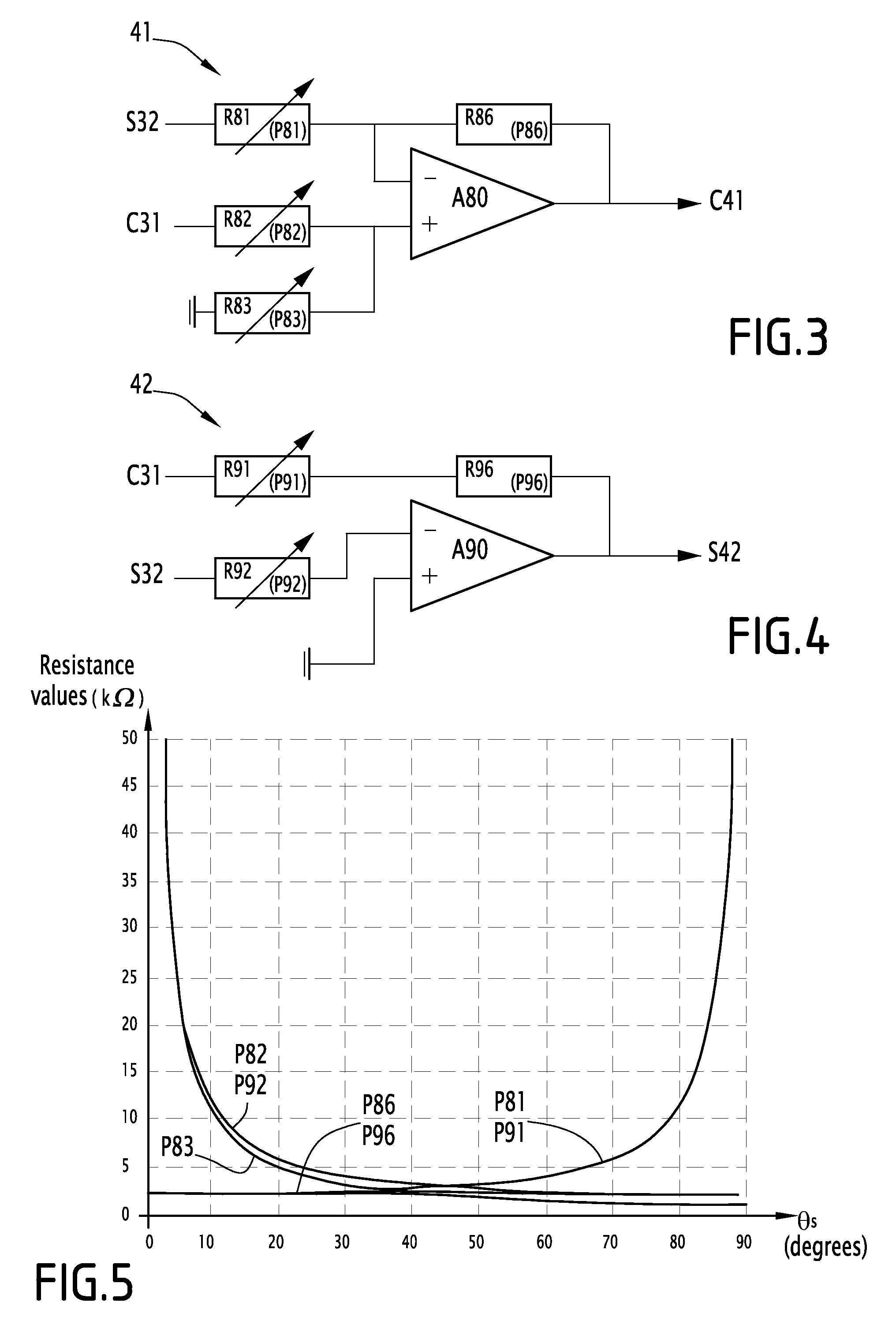
[0019]Thanks to the invention, electrical angular offset may be shifted without needing a precise indexation of mechanical angular offset. Moreover, no intervention of the user inside the software of a complex controller is needed. Advantageously, the shifter circuit and the control means can be added to an existing sensor device, without modifying this sensor device and its inner components. With the simple, cheap and efficient system and method according to the invention, a maximum realizable shift of almost 90 degrees can be obtained, as detailed hereafter.

Problems solved by technology

Some customers using sensor-bearing units do not have a lot of experience and knowledge on the motor control strategies and therefore use off-the-shelve solutions.
These solutions often only accept a very precise indexation of the sensor-bearing output signals with the rotor magnetic field.
These methods are difficult and costly to implement since they involve a precise mechanical indexation.
Such a method is difficult to implement and requires specific tooling for precise indexation of mechanical angular offset.

Method used


Image

  • System for delivering at least one shifted analogical output signal
  • System for delivering at least one shifted analogical output signal
  • System for delivering at least one shifted analogical output signal

Examples


Embodiment Construction

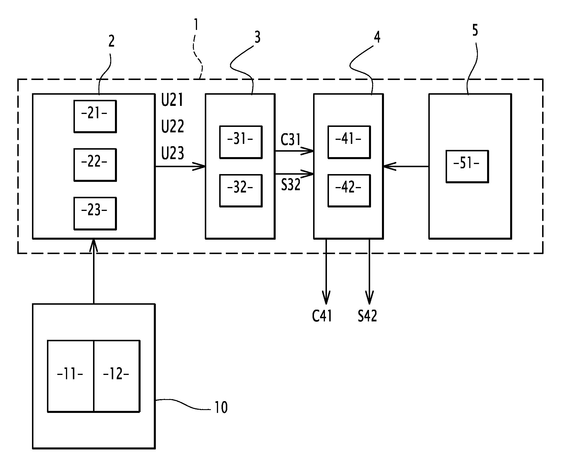
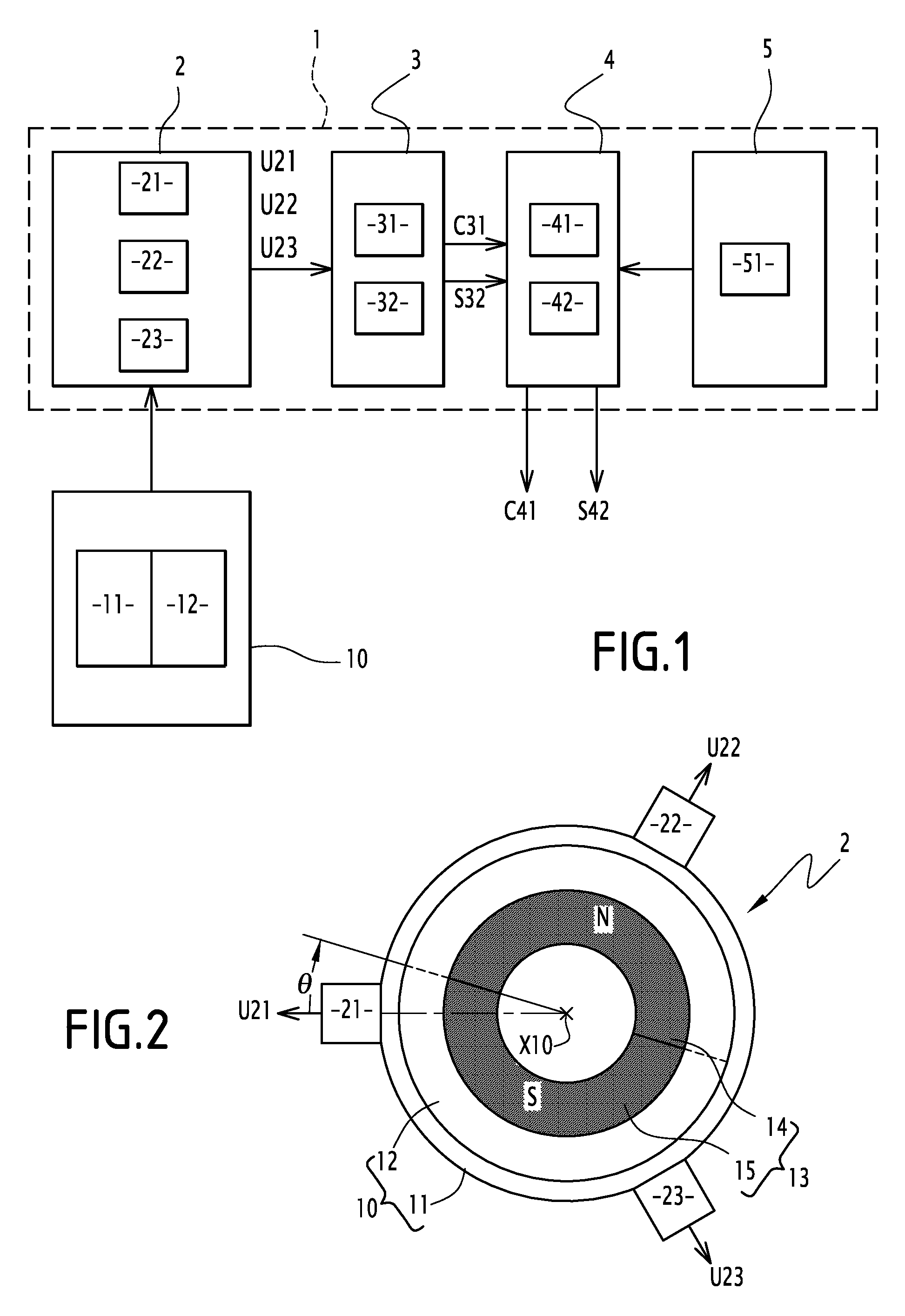
[0052]The system 1 shown on FIG. 1 may be implemented for shifting at least one analogical output signal C31 and / or S32 of a sensor device 2+3.

[0053]The system 1 comprises a sensor 2, a converter electronic circuit 3, a shifter electronic circuit 4 and control means 5. Sensor 2 and circuit 3 forms together the sensor device 2+3, which delivers the two analogical output signals C31 and S32. Sensor 2 cooperates with a mechanical device 10, while converter electronic circuit 3 cooperates with shifter electronic circuit 4 and control means 5, as detailed hereafter.

[0054]Preferably, sensor 2 and mechanical device 10 may be configured as the detection system described (FIG. 1 and associated description) in WO-A-2007 / 077389, while the circuit 3 may be configured as the electronic processing circuit described (FIG. 3 and associated description) in WO-A-2007 / 077389, which is incorporated herein by reference

[0055]As shown on the example of FIGS. 1 and 2, sensor 2 includes three detection cell...


PUM


Abstract

A sensor device analogical output signal shifting system including the sensor device including at least two detection cells adapted to equip a mechanical device and deliver at least two analogical output signals depending on behavior of the mechanical device. A shifter circuit selectively processes the analogical output signals and including at least a first part including at least one passive analogical component having a variable parameter and a second part including at least one passive analogical component having a variable parameter; and a control component for controlling the variable parameters of the passive analogical components, a variation of these variable parameters shifting at least one of the sensor device analogical output signals in the circuit. The circuit delivers at least two sensor device analogical output signals, including at least one shifted output signal including the first shifted analogical output signal and / or the second shifted sinusoidal signal of the sensor device.

Description

CROSS REFERENCE TO RELATED APPLICATIONS[0001]This is a United States National Stage Application claiming the benefit of International Application Number PCT / EP2013 / 050167 filed on 7 Jan. 2013 (07.01.2013), which is incorporated herein by reference in its entirety.TECHNICAL FIELD OF THE INVENTION[0002]The invention concerns a system and a method for shifting at least one analogical output signal of a sensor device. The invention also concerns a sensor-bearing unit including a bearing and such a system. The invention also concerns a shifter module.BACKGROUND OF THE INVENTION[0003]It is known to equip a mechanical device, such as a motor including a rotor and a stator, with a sensor-bearing unit for tracking the rotation of the rotor relative to the stator. Other mechanical devices including a mobile part and a stationary part may be equipped with such a sensor device, for example power steering, alternator and rack rails devices. Depending on the mechanical device, the mobile part may...

Claims


Application Information

Patent Timeline
Patent Type & Authority Patents(United States)
IPC IPC(8): G01D5/12F16C41/00G01P3/489G01D5/244G01P3/487G01P3/44
CPCG01D5/12F16C41/00G01D5/2448G01P3/487G01P3/489G01P3/443G01D2205/26
Inventor HUBERT, MATHIEUBLOKLAND, SUZANNE
Owner AB SKF
Learn More