
Self bonding floor tile

a self-bonding, floor tile technology, applied in the field of ground decoration materials, can solve the problems of increasing high replacement cost, and inability to be replaced, and achieve the effect of facilitating removal, and reducing the installation cost of the present floor til

Active Publication Date: 2017-02-07
FLOORING IND LTD
View PDF13 Cites 0 Cited by
  • Summary
  • Abstract
  • Description
  • Claims
  • Application Information

AI Technical Summary

Benefits of technology

The present invention provides a self bonding floor tile that can be quickly installed, easily replaced, and at low cost. The floor tile has a fiber-based self bonding layer that allows for easy removal and replacement of individual tiles. The floor tile is designed to bond securely to the support body but can be easily removed without leaving any adhesive on the support body. This simplifies the replacement process and makes the floor tile a cost-effective option for repair or replacement.

Problems solved by technology

The woodiness floor tiles are interlocked with each other into one piece, if some of the floor tiles are damaged and need to be replaced, the whole floor needs to be replaced, which causes high replacement cost.
The natural stone floor tiles are adhered to the ground by cement, once the floor tiles are installed, they cannot be replaced except for destroying them.
Furthermore, such present floor tiles have a common shortcoming of need to be installed by special technical workers, which increases the installation cost of the present floor tiles.
Because the opposite sides of the floor tiles are coated with adhesive, and the floor tiles are generally long, it is uneasy to place the floor tiles at the right position during adhering; furthermore, once two floor tiles are joined together, it is hard to reregulate their positions.
Thus, the worker could not make sure of an accurate and perfect installation, thereby influencing the usage of the floor.
Moreover, because the working surfaces of the floor tiles are joined together as a single piece, the problem of localised replacement still cannot be well resolved.

Method used


Image

  • Self bonding floor tile
  • Self bonding floor tile
  • Self bonding floor tile

Examples


Embodiment Construction

[0017]The present invention will now be described more specifically with reference to the following embodiments. It is to be noted that the following descriptions of preferred embodiments of this invention are presented herein for purpose of illustration and description only. It is not intended to be exhaustive or to be limited to the precise form disclosed.

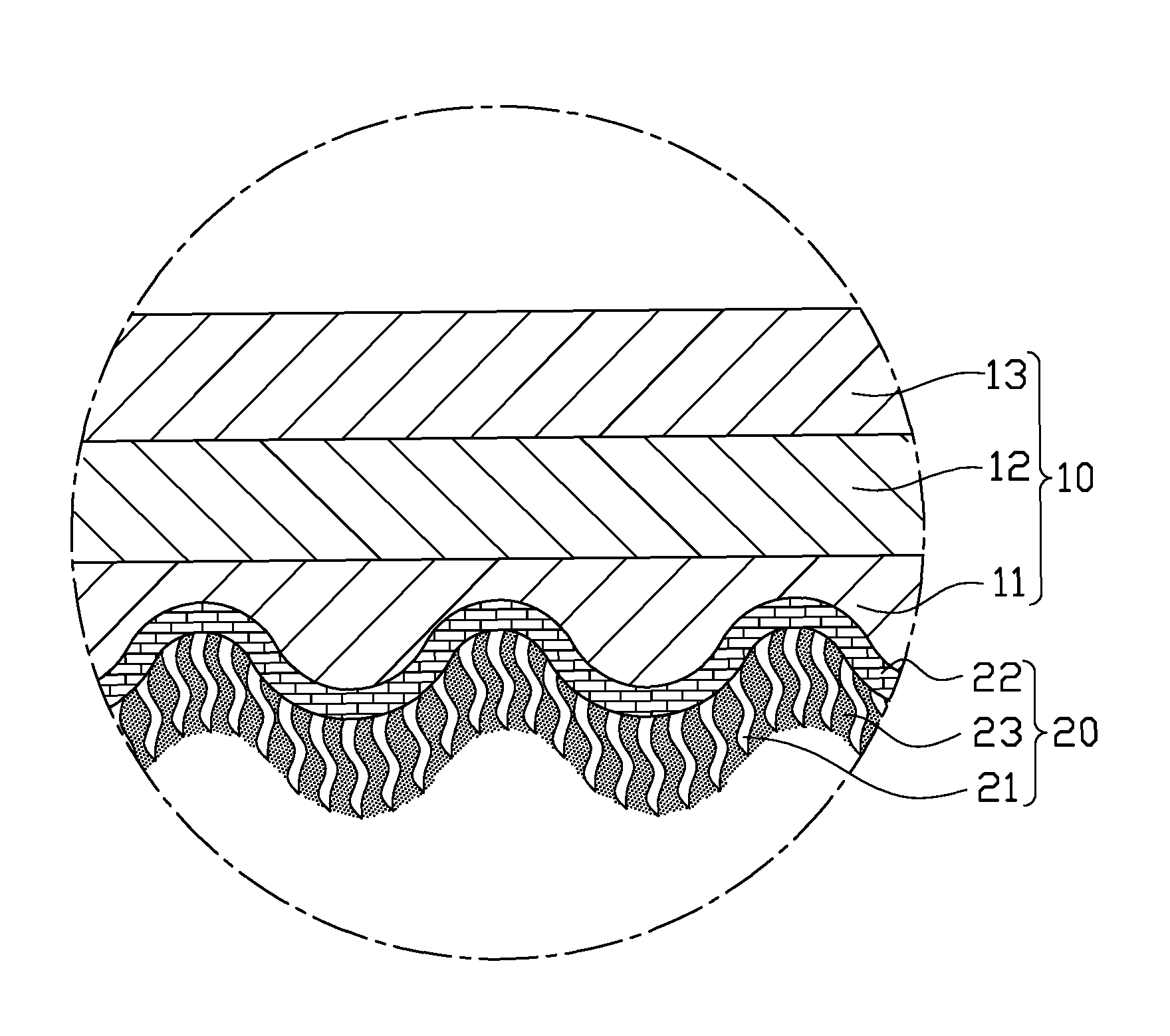
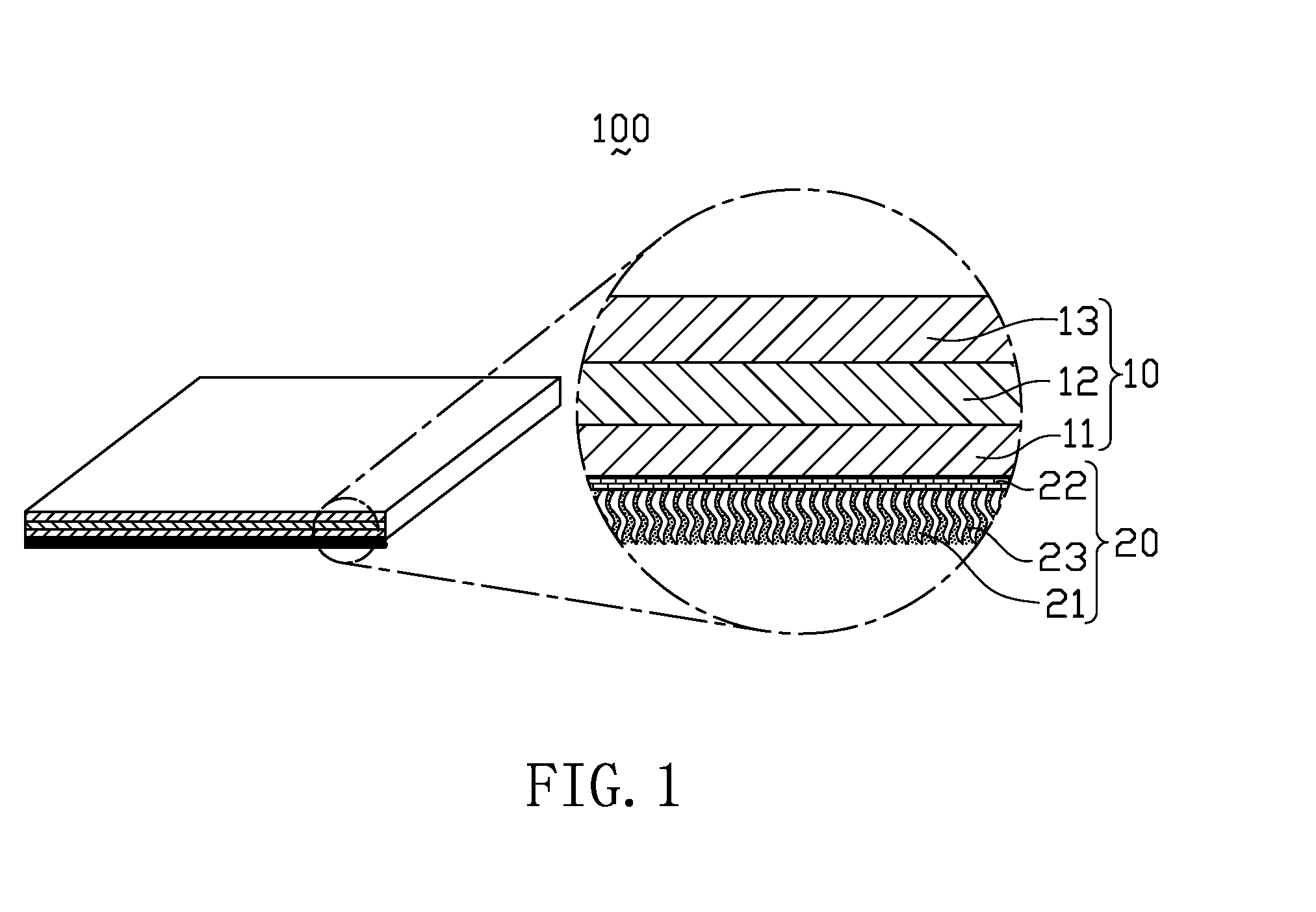
[0018]FIG. 1 is a cross sectional view of a self bonding floor tile according to an embodiment of the present invention, with a part of the self bonding floor tile enlarged. Referring to FIG. 1, the self bonding floor tile 100 of the present invention includes a main body 10 and a self bonding layer 20.

[0019]The main body 10 is the core layer of the self bonding floor tile 100; the hardness, weight and other physical characteristics are decided by the main body 10. The main body 10 is a PVC body and includes a base layer 11, a decoration layer 12 and a wear-resistant layer 13.

[0020]The base layer 11 may be composed of one layer o...


PUM

PropertyMeasurementUnit
lengthaaaaaaaaaa
lengthaaaaaaaaaa
temperatureaaaaaaaaaa

Abstract

A self bonding floor tile includes a main body and a self bonding layer connected with the main body. The self bonding layer includes an absorptive element, a first adhesive and a second adhesive. The first adhesive connects the main body with the self bonding layer. The absorptive element includes a plurality of fibers which are implanted into the first adhesive by flocking process with at least a portion of the absorptive element extending into the first adhesive, and at least a portion of the second adhesive penetrates into the other portion of the absorptive element for connecting the self bonding layer with a support body going to be decorated. The present self bonding floor tile can be quickly installed, easily and partly replaced with low installation and replacement cost.

Description

CROSS-REFERENCE TO RELATED APPLICATIONS[0001]This is a continuation-in-part application of an application Ser. No. 12 / 944,718, filed Nov. 11, 2010, which claims benefit of Chinese patent application No. 201010522705.1, filed on Oct. 26, 2010. The entirety of the above-mentioned patent applications are hereby incorporated by reference herein and made a part of this specification.FIELD OF THE INVENTION[0002]The present invention relates to a ground decoration material, more particularly to a self bonding floor tile.BACKGROUND OF THE INVENTION[0003]With the improvements of living standards, people paid more attentions to home environments, as an important component of interior decoration, floor tile, of course, obtains more attentions. Presently, the widely used floor tiles comprise woodiness floor tile, natural stone floor tile, and composite floor tile, or etc. All of the currently installation manners used for various floor tiles have obvious shortcomings, which are described in det...

Claims


Application Information

Patent Timeline
Patent Type & Authority Patents(United States)
IPC IPC(8): E04F15/02E04C2/24E04F15/10B32B3/30B32B5/00B32B3/26
CPCE04F15/02155B32B3/263B32B3/30B32B5/00E04C2/24E04F15/0215E04F15/105E04F15/107B32B2419/04Y10T428/23914Y10T428/23943Y10T428/2457Y10T428/24579Y10T428/28Y10T428/2848
Inventor YU, HSIUNG-TIEHLEE, SHIH-CHUNG
Owner FLOORING IND LTD
Learn More