
Electromagnetic actuator and fluid valve with such an actuator

a technology of actuator and actuator body, applied in the direction of magnets, operating means/release devices of valves, magnetic bodies, etc., can solve the problems of large electric current, unfavorable pure proportional operation, and possible inability to meet the requirements of fluid valves, etc., to achieve precise manufacturing tolerances, reduce the effect of manufacturing costs and extensive quality control

Active Publication Date: 2017-01-31
ZF FRIEDRICHSHAFEN AG
View PDF16 Cites 5 Cited by
  • Summary
  • Abstract
  • Description
  • Claims
  • Application Information

AI Technical Summary

Benefits of technology

[0017]Through the dipping of the second tapering in the second dipping stage, an axial covering between this tapering and the dipping stage is produced, and a radial air gap between them is reduced, and minimized in particular. Thus, a magnetic flux between the armature and the magnetic yoke is enlarged, and the actuating force that is generated increases. Given that the armature is able to move along the second tapering without colliding with it, it is possible to position the second dipping stage in such a manner that the second tapering is dipped in it earlier than in the state of the art. Thus, a progressive increase in the actuating force is accordingly obtained earlier, and the actuating force path characteristic curve features a progressive increase in the actuating force relatively early.
[0020]In one additional form of the invention, the armature is designed in a cylinder shape, with a maximum external diameter, and the second dipping stage is designed in a hollow cylinder shape, with a minimum internal diameter. Thereby, the maximum external diameter of the armature is smaller than the minimum internal diameter of the second dipping stage. Such armature and dipping stages can be easily produced. In one arrangement thereof, upon the dipping of the second tapering in the second dipping stage, that area of the armature that features the maximum external diameter is covered with that area of the second dipping stage that features the minimum internal diameter, in the direction of actuation (thus, axially), such that a radial gap between the armature and the second dipping stage is minimized. In the area of the second tapering, the armature is accordingly reduced from the maximum external diameter to a smaller external diameter.
[0028]In one arrangement thereof, the second part valve features a hollow cone-shaped valve seat, on which only one taper area, or some of several taper areas, of the closing element lie flat in the closed state of the second part valve. The manufacturing of the fluid valve is thereby simplified, as it is then the case that not all taper areas need to lie flat on the valve seat; this would require very precise manufacturing tolerances (precise tools, extensive quality checks, etc.).

Problems solved by technology

However, in some situations, such a purely proportional manner of operation is not advantageous.
In order to then set a proportional pressure control valve at a high fluid pressure, given the flat p / I characteristic curve, a very large electric current is necessary, which is possibly not available.

Method used


Image

  • Electromagnetic actuator and fluid valve with such an actuator
  • Electromagnetic actuator and fluid valve with such an actuator
  • Electromagnetic actuator and fluid valve with such an actuator

Examples


Embodiment Construction

[0036]Reference will now be made to embodiments of the invention, one or more examples of which are shown in the drawings. Each embodiment is provided by way of explanation of the invention, and not as a limitation of the invention. For example features illustrated or described as part of one embodiment can be combined with another embodiment to yield still another embodiment. It is intended that the present invention include these and other modifications and variations to the embodiments described herein.

[0037]In the figures, equivalent or at least functionally equivalent components are provided with the same reference signs.

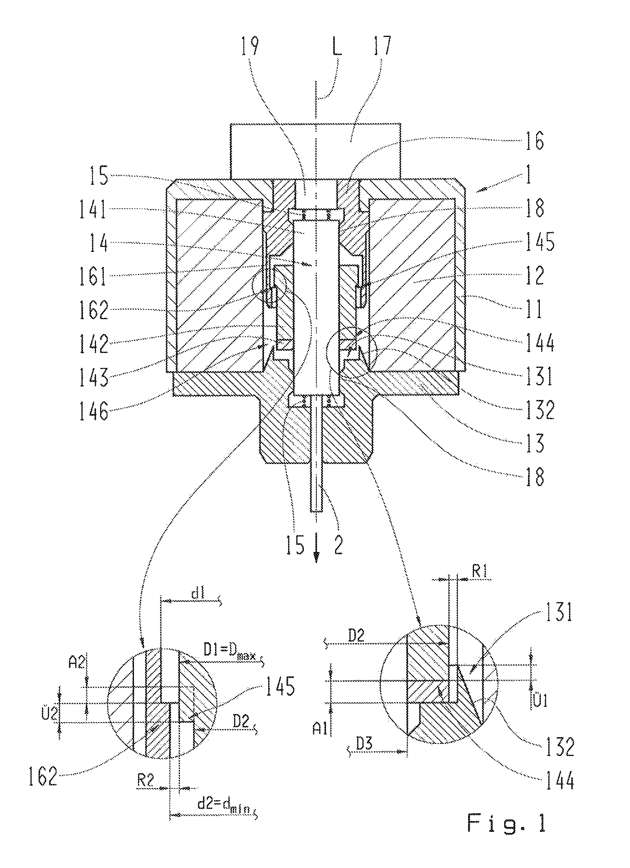
[0038]FIG. 1 shows a longitudinal section through an electromagnetic actuator 1 designed in accordance with the invention. This features a housing 11, a solenoid coil 12, a solenoid armature 14 and a magnetic yoke 13, 16. The first part 13 of the magnetic yoke, which is provided in the area of a first front side of the solenoid armature 14, has a first dipping ...


PUM

PropertyMeasurementUnit
taper angleaaaaaaaaaa
angleaaaaaaaaaa

Abstract

An electromagnetic actuator with at least one solenoid coil, one armature, which is magnetically movable by means of the solenoid coil in an armature area and has a first and a second tapering, and a magnetic yoke. The yoke has a first dipping stage in which the first tapering of the armature is dipped upon a shifting of the armature in a direction of actuation, and a second dipping stage in which the second tapering of the armature is dipped upon a shifting of the armature in the direction of actuation. A maximum radial external dimension of the armature in the area of the second tapering is smaller than a minimum radial internal dimension of the second dipping stage. In addition, the invention refers to a fluid valve that is actuated by means of the electromagnetic actuator.

Description

FIELD OF THE INVENTION[0001]The invention relates to an electromagnetic actuator, in particular for the actuation of a fluid valve, as well as a fluid valve with such an actuator.BACKGROUND[0002]With multi-stage vehicle automatic transmissions and automatic vehicle manual transmissions known from conventional use, hydraulic shifting elements designed as clutches or brakes are used for inserting different transmission stages of the transmission. In this process, for changing or inserting a desired transmission stage of the transmission, the hydraulic shifting elements are pressurized or vented with fluid pressure (fluid pressure is relieved). Fluid valves, in particular pressure control valves, are used for this purpose.[0003]The current standard fluid valves for vehicle transmissions, for example, that which is disclosed in WO 2005 / 026858 A1, has two poppet valves interconnected at a hydraulic half-bridge circuit. Such a fluid valve has an inlet opening and two outlet openings, wher...

Claims


Application Information

Patent Timeline
Patent Type & Authority Patents(United States)
IPC IPC(8): F16K31/06F16K1/54H01F7/06
CPCF16K31/06F16K1/54F16K31/0634F16K31/0637F16K31/0675H01F7/06H01F7/08H01F7/1607
Inventor MAYR, KARLHEINZMOOSMANN, MARKUS
Owner ZF FRIEDRICHSHAFEN AG
Learn More