
Ultra-wideband biconical antenna with excellent gain and impedance matching

a biconical antenna, ultra-wideband technology, applied in the direction of resonant antennas, waveguide horns, antenna feed intermediates, etc., can solve the problems of affecting the direction of the antenna, and causing the null or minimum in the direction of the vehicl

Active Publication Date: 2017-01-24
HER MAJESTY THE QUEEN AS REPRESENTED BY THE MINIST OF NAT DEFENCE OF HER MAJESTYS CANADIAN GOVERNMENT
View PDF15 Cites 1 Cited by
  • Summary
  • Abstract
  • Description
  • Claims
  • Application Information

AI Technical Summary

Problems solved by technology

Several dipole-types antennas, forming an antenna farm, have been used with some success but they create a clutter on the vehicle and can interfere with each others.
For a single-antenna solution, the bicone has been used by many manufacturers but the problem is that, for ultra-wideband, the beam splits in two parts over some frequency bands and creates nulls or minimums in the directions of interest.
Also, it is difficult to maintain a good impedance match over such ultra-widebands.

Method used


Image

  • Ultra-wideband biconical antenna with excellent gain and impedance matching
  • Ultra-wideband biconical antenna with excellent gain and impedance matching
  • Ultra-wideband biconical antenna with excellent gain and impedance matching

Examples


Embodiment Construction

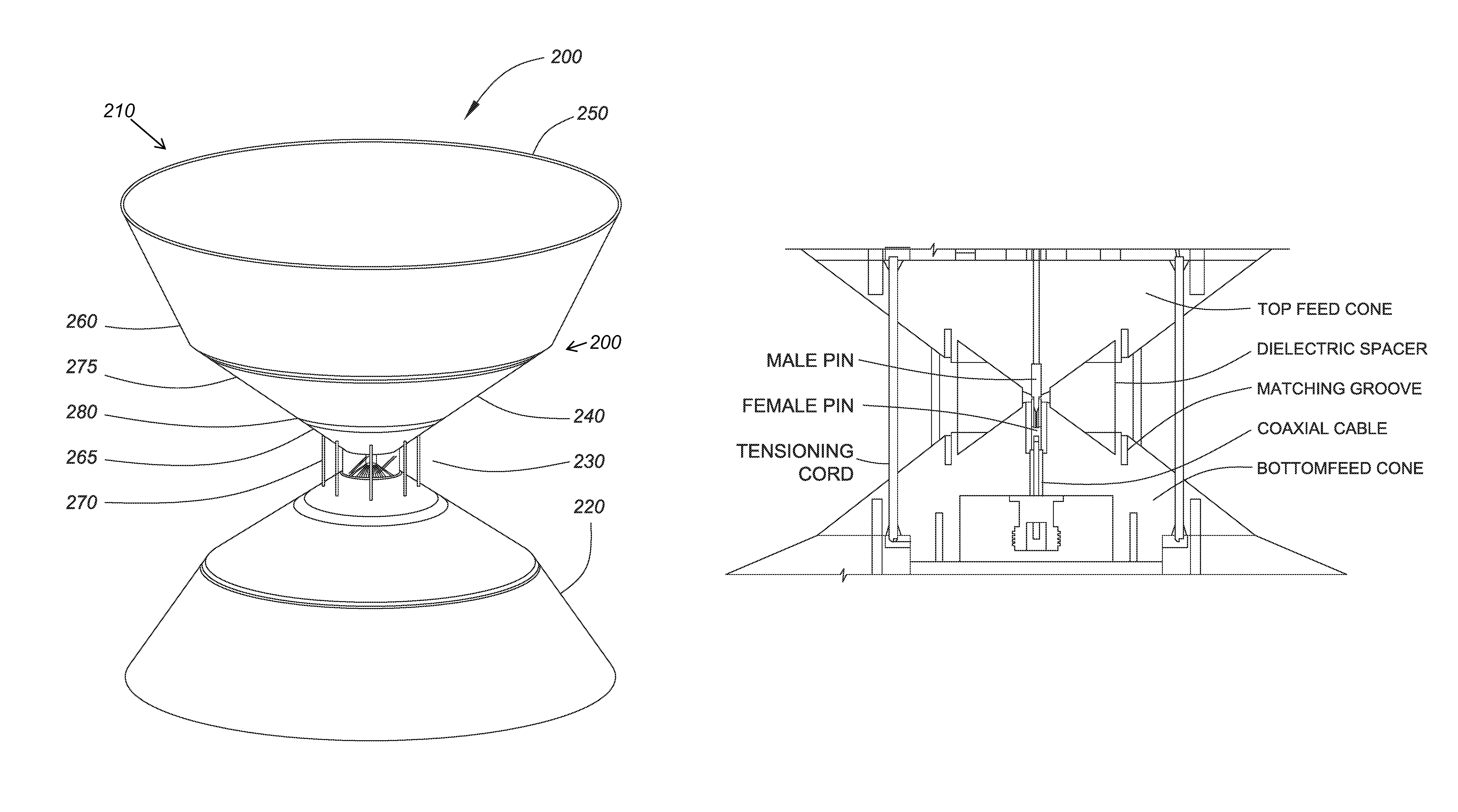
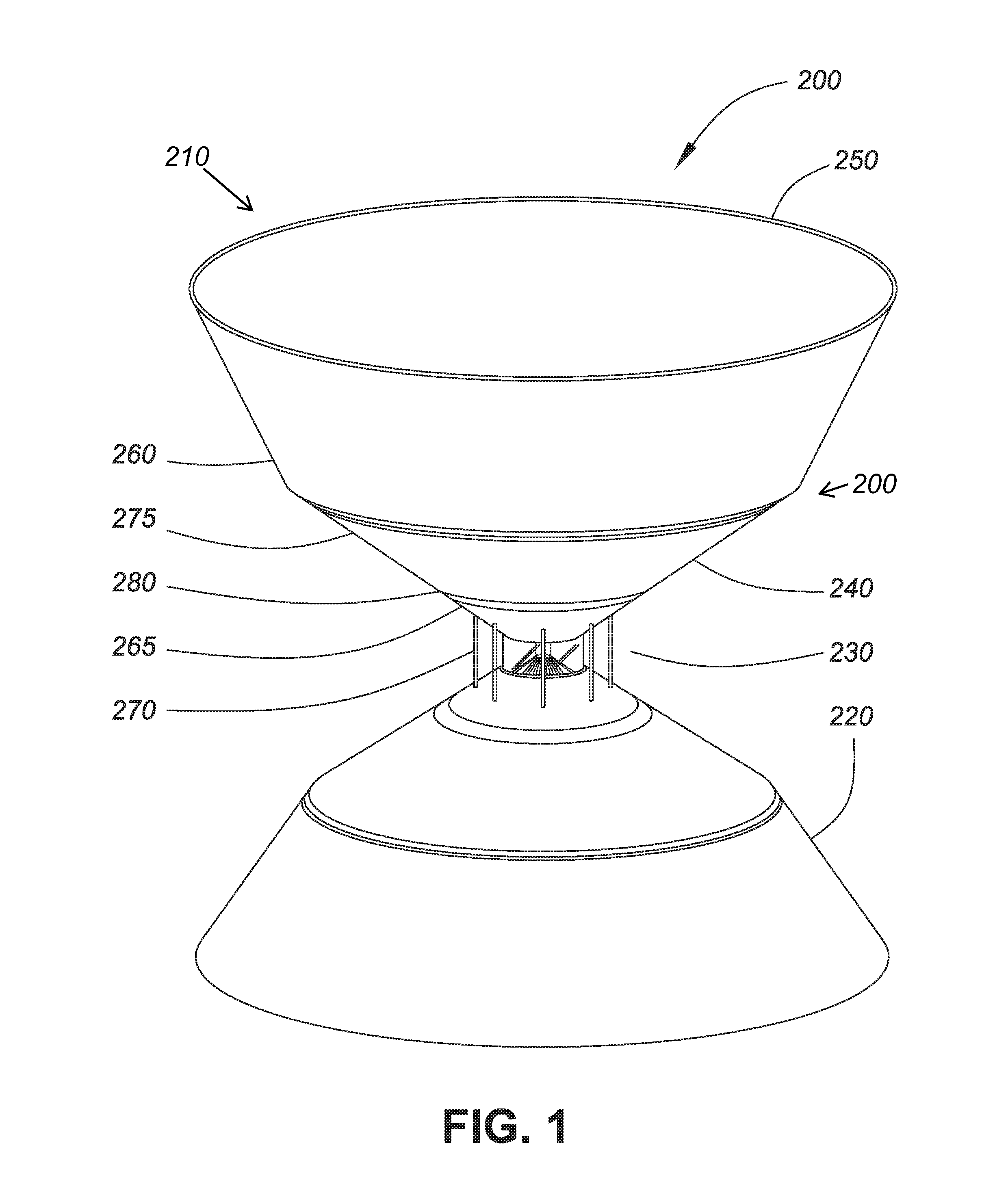
[0064]Referring to FIG. 1, a side view of a biconical antenna 200 according to one aspect of the invention is illustrated. The antenna 200 has a top antenna assembly 210 and a bottom antenna assembly 220, both of which are coupled to a dielectric spacer 230 at the apex of each of the antenna assemblies 210, 220.

[0065]The parts of the top antenna assembly are similar to the parts of the bottom antenna assembly and, for simplicity, only the parts of the top antenna assembly will be discussed. The assembly 210 has a middle cone 240 and a topmost cone 250. The middle cone 240 and the topmost cone 250 are connected at the rim 260 of the middle cone 240. The rim 260 can also be seen as a chine or a ridge or sharp intersection between a side and a bottom. It should be noted that the middle cone 240 is a cone with its apex terminating at the dielectric spacer 230. The topmost cone 250 is a truncated cone which, if it was a complete cone, has an angle of opening smaller than the cone's angle...


PUM


Abstract

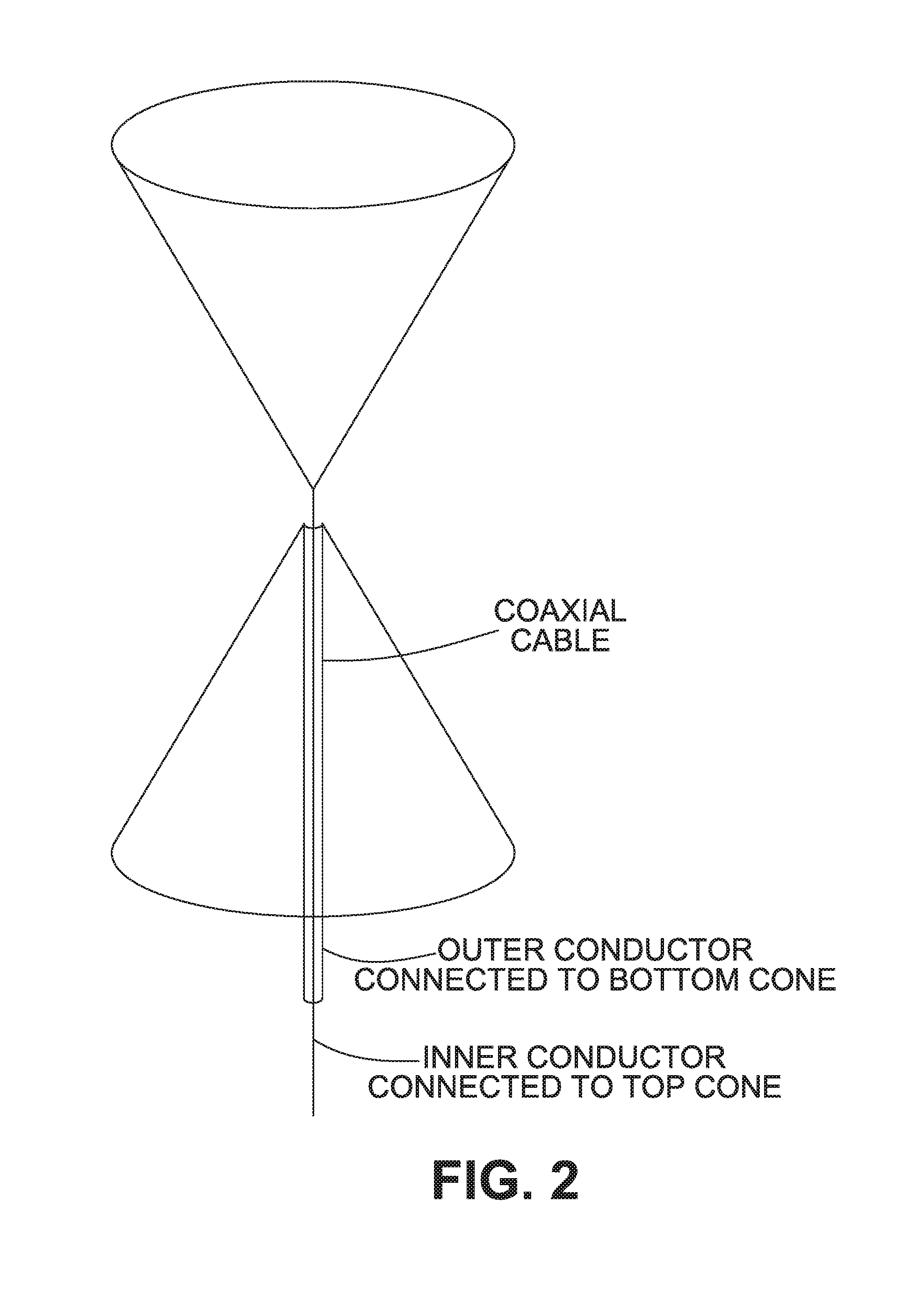
Systems and devices relating to a biconical antenna. The antenna has a top cone assembly and a bottom cone assembly, each cone assembly being coupled to a dielectric spacer at its apex. Each cone assembly has a cone section and a truncated cone section. The cone section is a cone with an apex which forms the apex of the cone assembly. The truncated cone section is coupled to the cone of the cone section at the cone's rim. The cone has an opening angle which is larger than the opening angle of the truncated cone. The biconical antenna can be fed by way of a coaxial cable with the outer cable feeding the bottom cone assembly and the inner cable feeding the top cone assembly.

Description

TECHNICAL FIELD[0001]The present invention relates to antennas. More specifically, the present invention relates to an antenna design for use in ultra-wideband applications.BACKGROUND[0002]Many applications require wideband antennas. Some of these applications are military related and may need an ultra-wideband antenna with an omni-directional pattern and which can be used to illuminate the ground around a vehicle for jamming radio control signals. These radio control signals may be used to detonate improvised explosive devices.[0003]Several dipole-types antennas, forming an antenna farm, have been used with some success but they create a clutter on the vehicle and can interfere with each others. For a single-antenna solution, the bicone has been used by many manufacturers but the problem is that, for ultra-wideband, the beam splits in two parts over some frequency bands and creates nulls or minimums in the directions of interest. Also, it is difficult to maintain a good impedance m...

Claims


Application Information

Patent Timeline
Patent Type & Authority Patents(United States)
IPC IPC(8): H01Q9/28H01Q13/04
CPCH01Q9/28H01Q13/04
Inventor MORIN, GILBERT A.RYAN, LARRY
Owner HER MAJESTY THE QUEEN AS REPRESENTED BY THE MINIST OF NAT DEFENCE OF HER MAJESTYS CANADIAN GOVERNMENT
Learn More