
Illumination device

Active Publication Date: 2017-01-10
PARAGON SEMICON LIGHTING TECH
View PDF6 Cites 2 Cited by
  • Summary
  • Abstract
  • Description
  • Claims
  • Application Information

AI Technical Summary

Benefits of technology

The present invention is an illumination device that uses a sensor module or control module to continuously emit light to enhance its convenience. The device consists of a first and second illumination module, with the second module acting as an auxiliary light source. When activated, the second module emits light to catch the user's attention. The sensor module detects an invading object and controls the switching unit to turn on the first module. The illumination device also includes a dimming module for adjusting the brightness setting. This invention aims to provide a more convenient and efficient illumination device.

Problems solved by technology

Therefore, the passerby or the third party is shocked by the sudden light to even fall down, crash or get hurt.
It is inconvenient to use such an induction lighting apparatus.

Method used


Image

  • Illumination device
  • Illumination device
  • Illumination device

Examples


Embodiment Construction

[0017]The detailed description set forth below in connection with the appended drawings is intended as a description of certain embodiments of the present disclosure, and is not intended to represent the only forms that may be developed or utilized. The description sets forth the various functions in connection with the illustrated embodiments, but it is to be understood, however, that the same or equivalent functions may be accomplished by different embodiments that are also intended to be encompassed within the scope of the present disclosure.

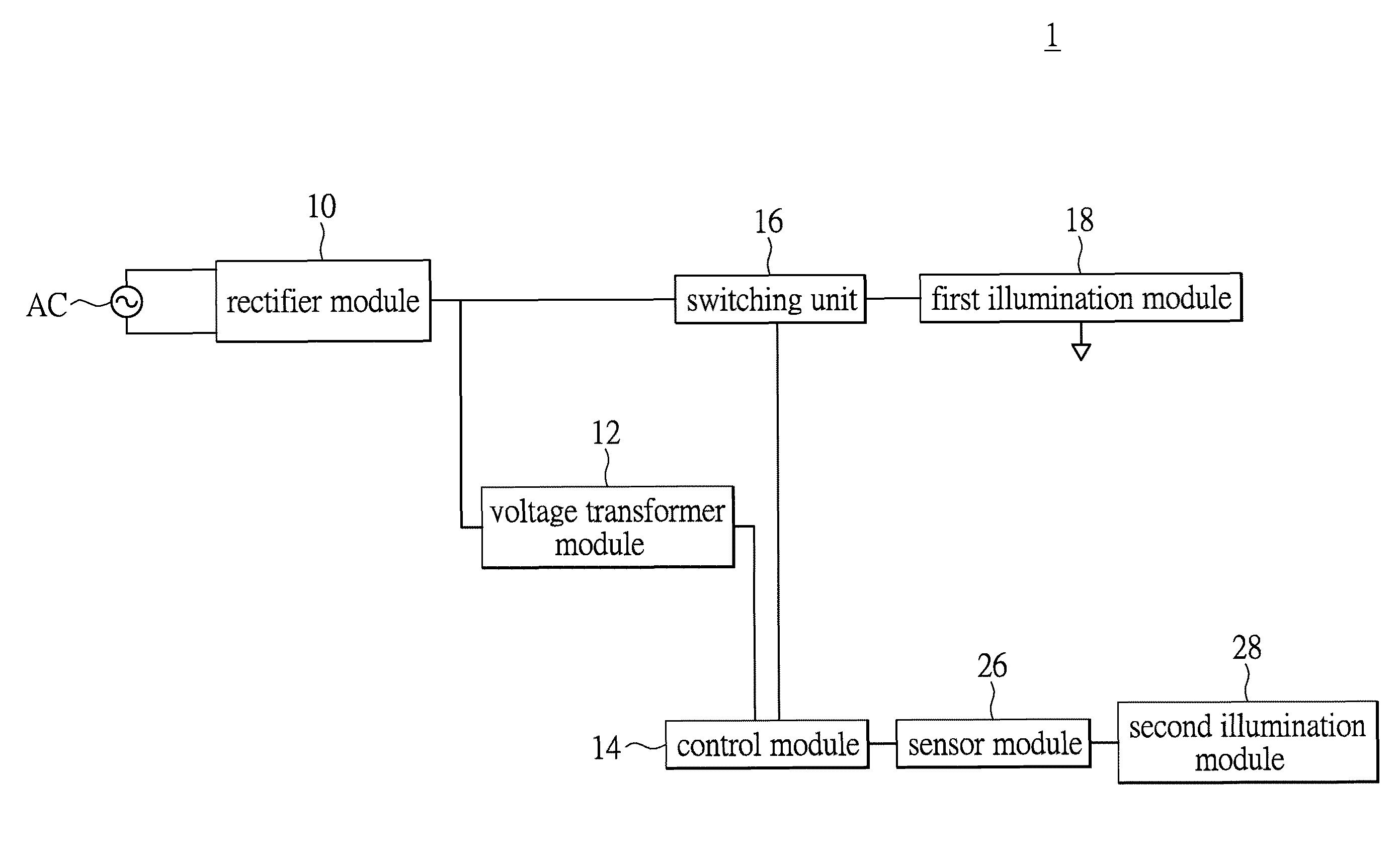
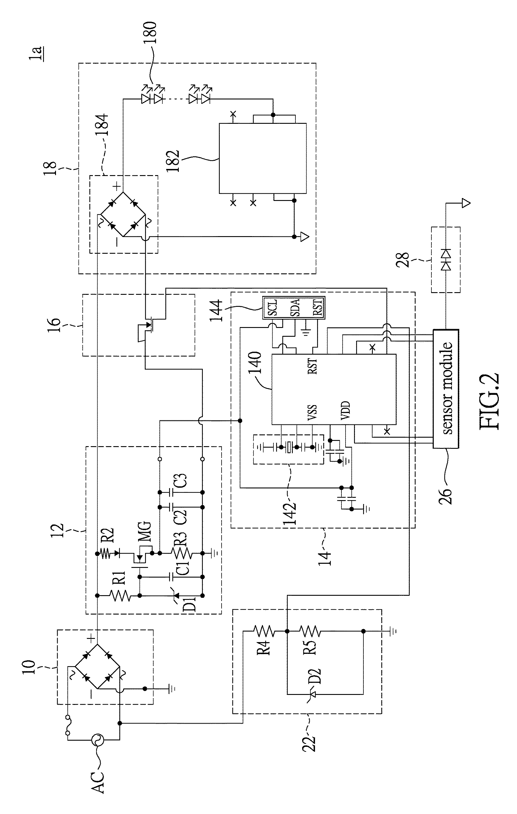
[0018]FIG. 1 is a block diagram of an illumination device according to one embodiment of the present invention. Referring to FIG. 1, an illumination device 1 is electrically connected to an alternate current (AC) power source AC. The alternate current power source AC outputs an input voltage that has been rectified by a rectifier module 10. The illumination device 1 includes a voltage transformer module 12, a switching unit 16, a control modu...


PUM


Abstract

An illumination device including a voltage transformer module, a switching unit, a control module, a sensor module, a first illumination module and a second illumination module. The switching unit is coupled to the rectifier module and the voltage transformer module. The control module is coupled to the switching unit and the voltage transformer module. The sensor module is electrically connected to the control module. The sensor module senses an invading object within an induction area. The first illumination module is electrically connected to the switching unit. The second illumination module is electrically connected to the sensor module. The sensor module supplies electricity to the second illumination module to emit light. The sensor module outputs a sensing signal to the control module when the sensor module senses the invading object. The control module controls the switching unit to be turned on so that the first illumination module emits light.

Description

BACKGROUND[0001]1. Technical Field[0002]The present invention generally relates to an illumination device and, more particularly, to an illumination device for lighting.[0003]2. Description of Related Art[0004]Since the light-emitting diode (LED) has advantages such as low power consumption, high luminance and long lifetime, it has been widely used in various lighting apparatuses. A lighting apparatus includes rectifier circuits, switches, illumination modules and a current source. The illumination module includes a plurality of light-emitting diodes connected in series. The rectifier circuit, for example, a full-wave rectifier circuit rectifies alternate current (AC) power to provide a pulsating direct current supplied to the light-emitting diode. When the light-emitting diodes connected in series are turned on, the current source supplies steady current to the light-emitting diodes in the illumination module.[0005]Generally, an induction lighting apparatus senses an invading objec...

Claims


Application Information

Patent Timeline
IPC IPC(8): H05B33/08H05B37/02H05B44/00
CPCH05B33/0815H05B37/0227H05B33/0845H05B33/0812H05B45/10H05B47/115Y02B20/40Y02B20/30
Inventor CHUNG, CHIA-TINTAI, SHIH-NENG
Owner PARAGON SEMICON LIGHTING TECH
Learn More