
Lacrimal duct therapy device

a lacrimal duct and duct technology, applied in the field of medical devices, can solve the problems of user's lacrimal duct blockage and/or pain, increased pain or damage, and difficulty in reducing pain or damage,

Active Publication Date: 2017-01-10
ADAIE HAMDAH J S
View PDF15 Cites 21 Cited by
  • Summary
  • Abstract
  • Description
  • Claims
  • Application Information

AI Technical Summary

Benefits of technology

The lacrimal duct therapy device is a device that is used to massage the lacrimal duct, which helps to improve its function. The device includes a frame assembly and an actuator assembly, which has a contact assembly and a motor assembly. The contact assembly has a cam member that is connected to the motor assembly and has a base portion and a lobe portion. The actuator assembly rotates the cam member, which causes the arm member to extend outward and apply pressure to the user's face. This helps to relax the user's facial muscles and improve the function of the lacrimal duct. The frame assembly can also include different arm members that attach to the user's ears and a bridge member that connects to the actuator assembly, making it easier to position the device on the user's head. The device can also have multiple cam members that are positioned in an alternating manner, which allows for different regions of the user's face to be massaged simultaneously. Overall, the device provides a simple and effective way to massage the lacrimal duct and improve its function.

Problems solved by technology

Occasionally, a user may suffer blockage and / or pain in the lacrimal duct.
Because the lacrimal duct is located above the nasal cavity, it can be difficult for the user to alleviate the blockage without forcing an evasive tool through the nose.
Such a procedure may force the blockage further into the lacrimal duct, causing more pain or damage, instead of alleviating the pressure or blockage.

Method used


Image

  • Lacrimal duct therapy device
  • Lacrimal duct therapy device
  • Lacrimal duct therapy device

Examples


Embodiment Construction

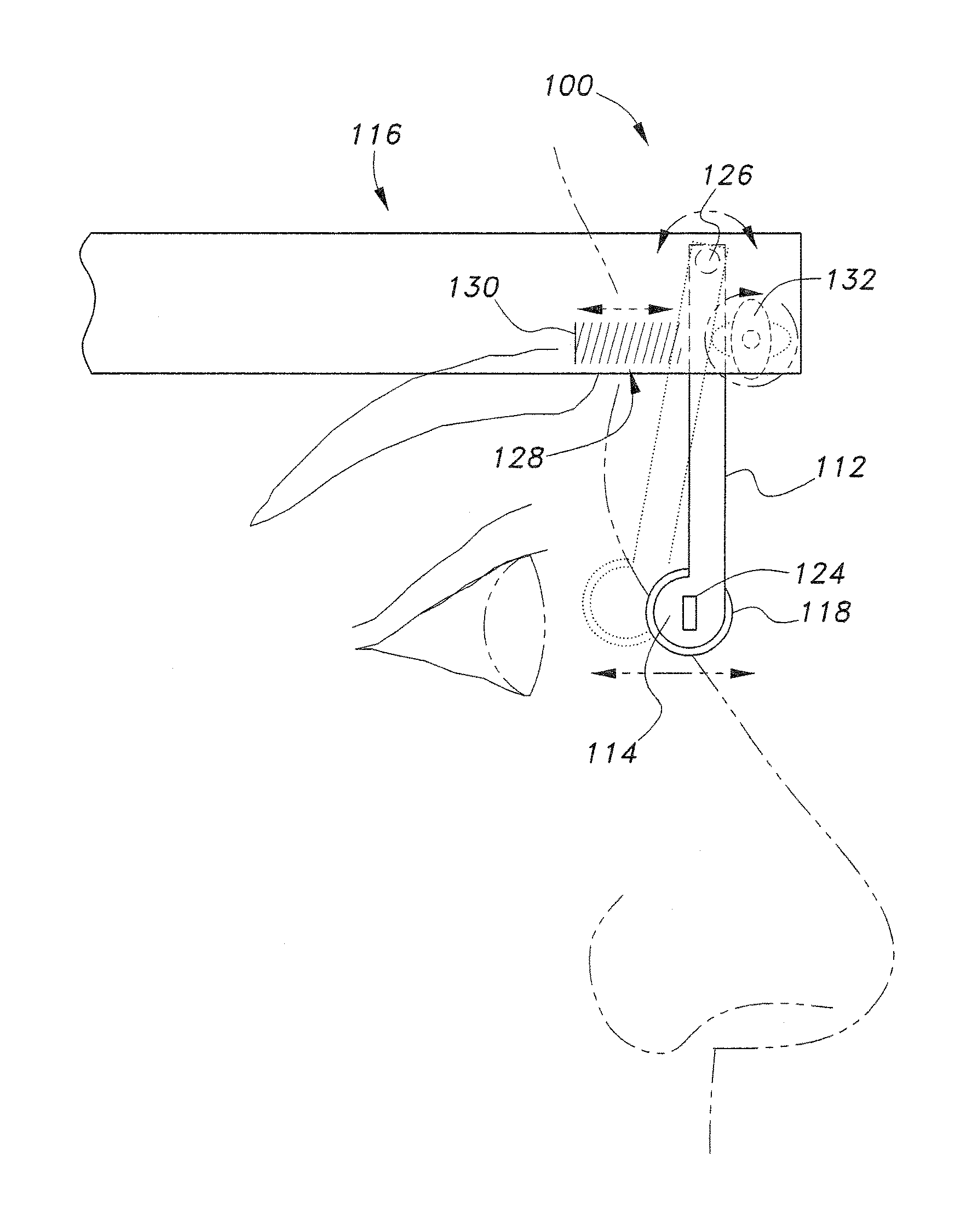
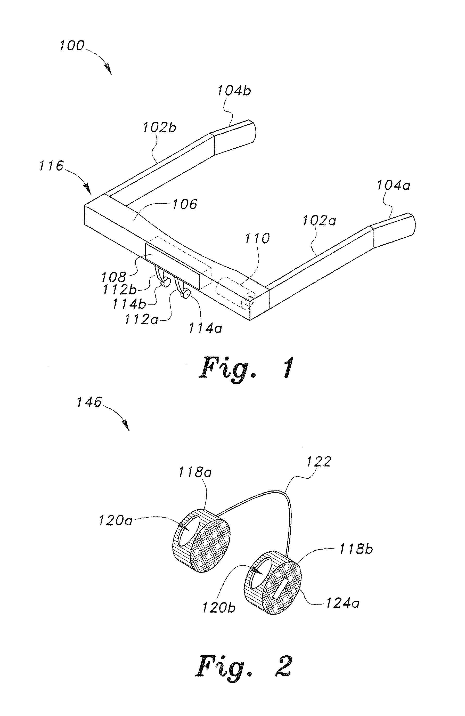
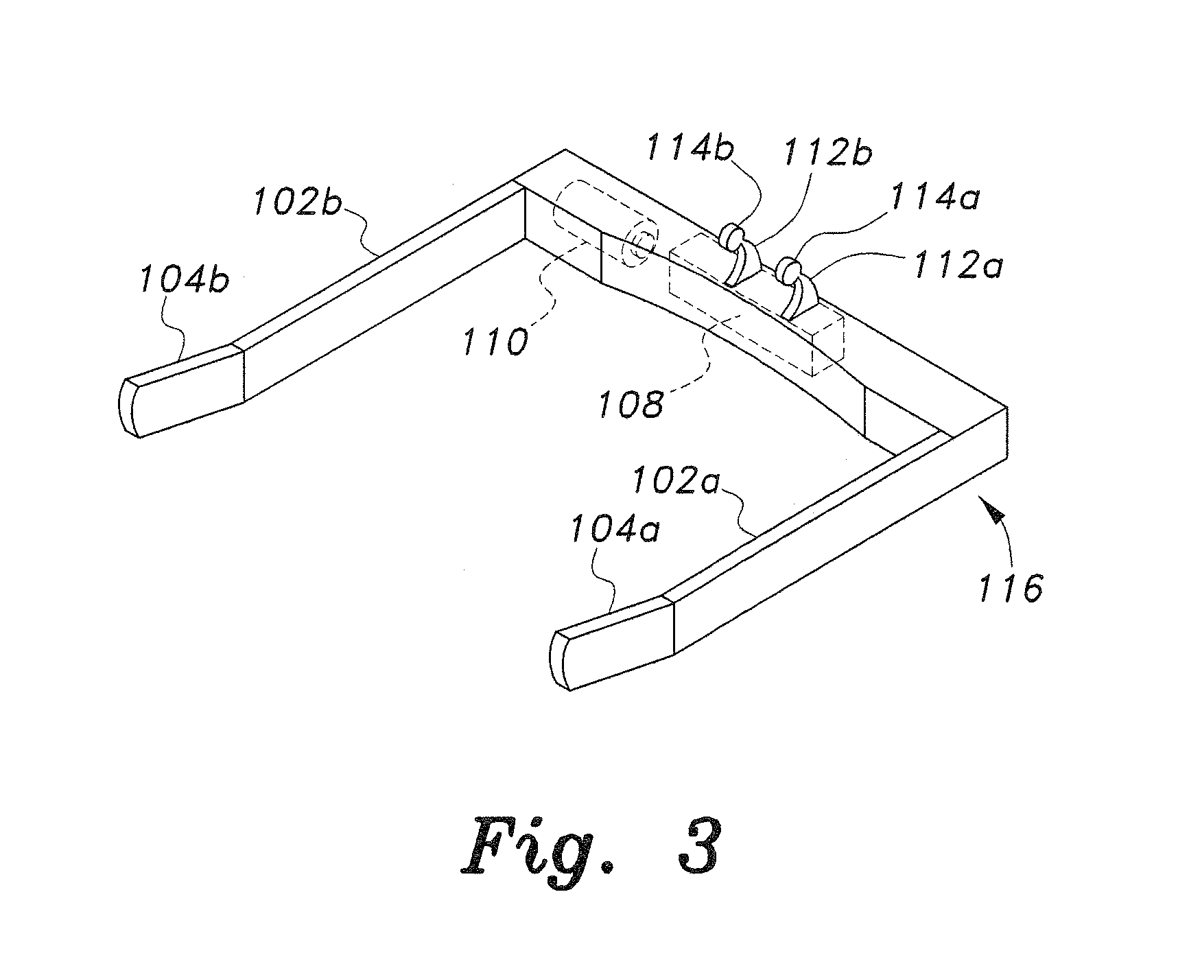
[0024]The lacrimal duct therapy device is configured to provide therapeutic massaging pressure to an external region of a user's face proximate to the lacrimal duct. Referring to FIGS. 1 and 3, the lacrimal duct therapy device 100 includes a frame assembly 116 and an actuator assembly 108 for providing a massaging and / or vibrational therapy to the lacrimal duct.

[0025]The frame assembly 116 may have a conventional eyeglass frame configuration, including dual arm members or support members 102a, 102b configured to engage temporal regions on opposing sides of the user's head, thereby permitting the device 100 to be removably affixed to the user's head. The frame assembly 116 further includes a bridge member 106 extending between the respective support members 102a, 102b and configured for engagement with the user's forehead region. Each support member 102a, 102b includes a respective ear latch member 104a, 104b, which are adaptable for latching engagement with the user's ears.

[0026]The...


PUM


Abstract

The lacrimal duct therapy device includes a frame assembly and an actuator assembly mounted on the frame assembly. The actuator assembly includes a contact assembly and a motor assembly configured to drive the contact assembly. The contact assembly includes at least one cam member having a base portion and a lobe portion and at least one arm member. The at least one cam member is mounted on a rod member attached to the motor assembly for rotation therewith. The at least one cam member bears against a leg member pivotally attached to the frame assembly, the leg member terminating in a knob bearing against the user's lacrimal duct region. Actuation of the motor periodically pivots the leg member so that the knob massages the lacrimal duct.

Description

BACKGROUND OF THE INVENTION[0001]1. Field of the Invention[0002]The present invention relates to medical devices, and more particularly to a lacrimal duct therapy device for providing therapy to alleviate pain and / or pressure in the user's lacrimal duct.[0003]2. Description of the Related Art[0004]The lacrimal duct (“nasolacrimal duct”) facilitates the movement of tears from a lacrimal sac into the nasal cavity. The opening of the nasolacrimal duct into the inferior nasal meatus is partially covered by a mucosal fold. Excess tears flow through the lacrimal duct, which drains into the inferior nasal meatus. The lacrimal duct is lined by stratified columnar epithelium containing mucus-secreting goblet cells and is surrounded by connective tissue.[0005]Occasionally, a user may suffer blockage and / or pain in the lacrimal duct. Because the lacrimal duct is located above the nasal cavity, it can be difficult for the user to alleviate the blockage without forcing an evasive tool through th...

Claims


Application Information

Patent Timeline
Patent Type & Authority Patents(United States)
IPC IPC(8): A61H23/00A61H5/00
CPCA61H23/006A61H23/004A61H5/00A61H2201/0207A61H2201/5097A61H2205/024A61H2201/1607A61H2205/023A61H2201/1604A61H7/004A61H23/0254A61H2201/1418A61H2201/165A61H2201/1676A61F9/00772A61M11/06
Inventor ADAIE, HAMDAH J. S.
Owner ADAIE HAMDAH J S
Learn More