
Quick release bracket assembly

a technology of quick release and assembly, which is applied in the direction of fastening means, server, and support structure mounting, can solve the problems of inconvenient installation and complicated front dismounting design, and achieve the effect of convenient quick mounting and dismounting and simple structur

Active Publication Date: 2016-12-27
NAN JUEN INT CO LTD
View PDF5 Cites 16 Cited by
  • Summary
  • Abstract
  • Description
  • Claims
  • Application Information

AI Technical Summary

Benefits of technology

The present invention is a quick release bracket assembly with a simple structure that allows for easy mounting and dismounting of a positioning plate. The assembly includes a bracket, a locating device, a positioning plate, and a locking device. The positioning plate is movable relative to the bracket and can be locked in place using the locking device. The assembly allows for quick mounting and dismounting of the bracket without having to fully detach the bracket from its current location. The technical effects include improved convenience and flexibility in mounting and dismounting of the bracket, which can be used in various applications.

Problems solved by technology

This front dismounting design is complicated and inconvenient to install.

Method used


Image

  • Quick release bracket assembly
  • Quick release bracket assembly
  • Quick release bracket assembly

Examples


Embodiment Construction

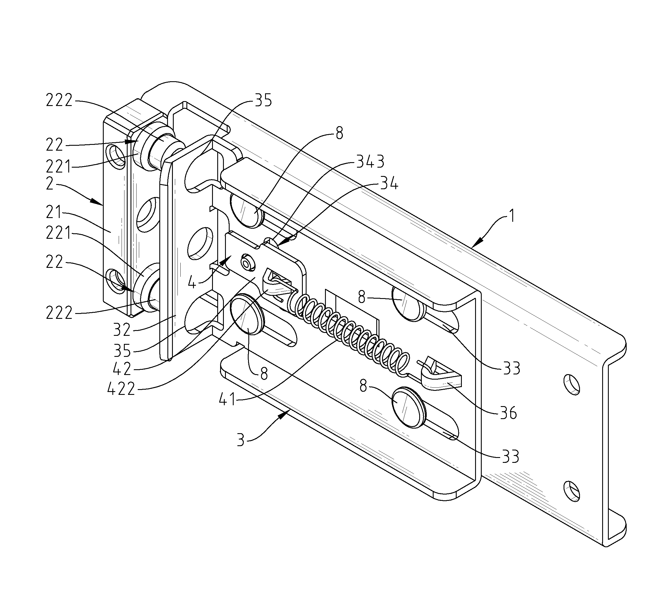
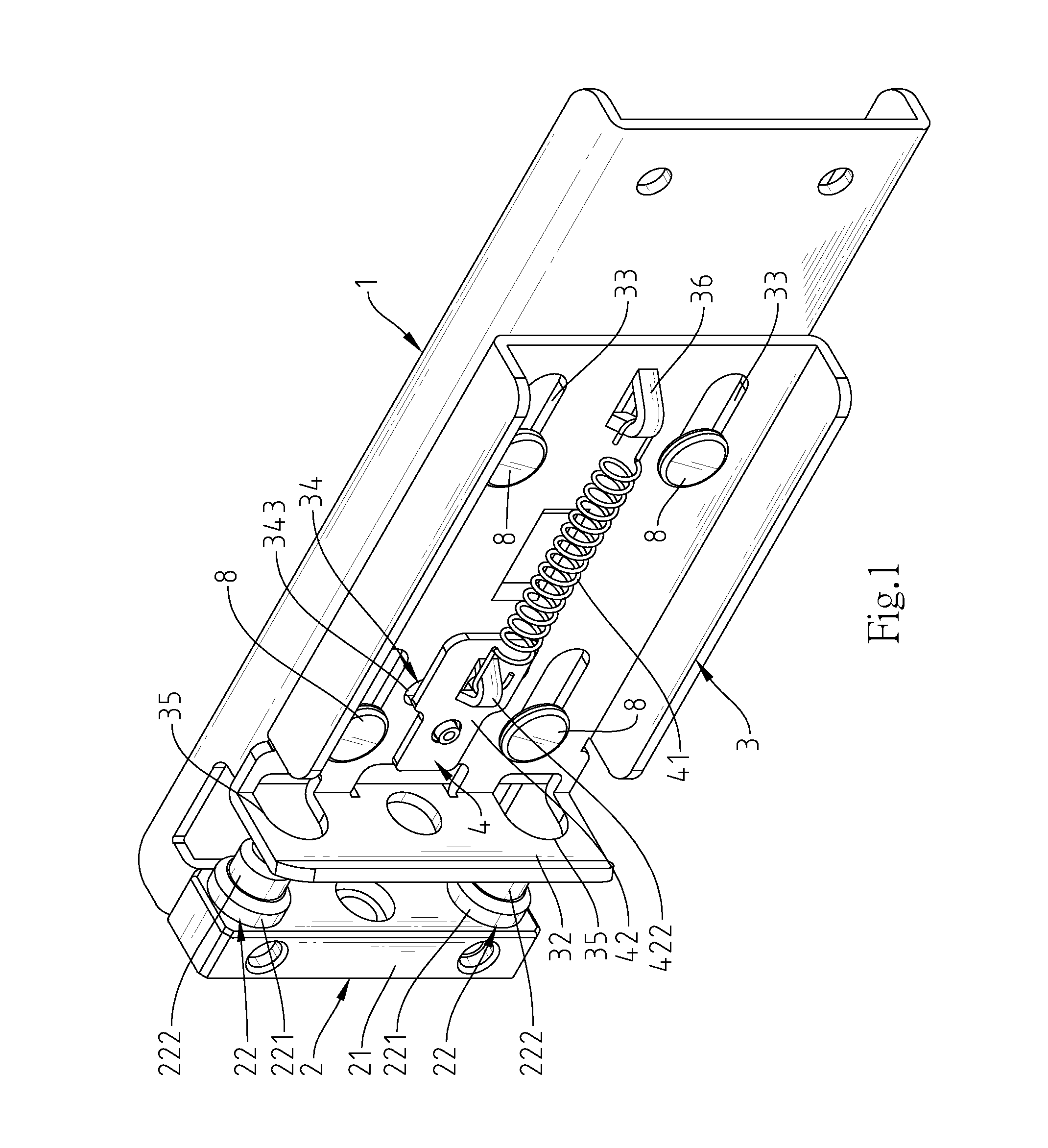
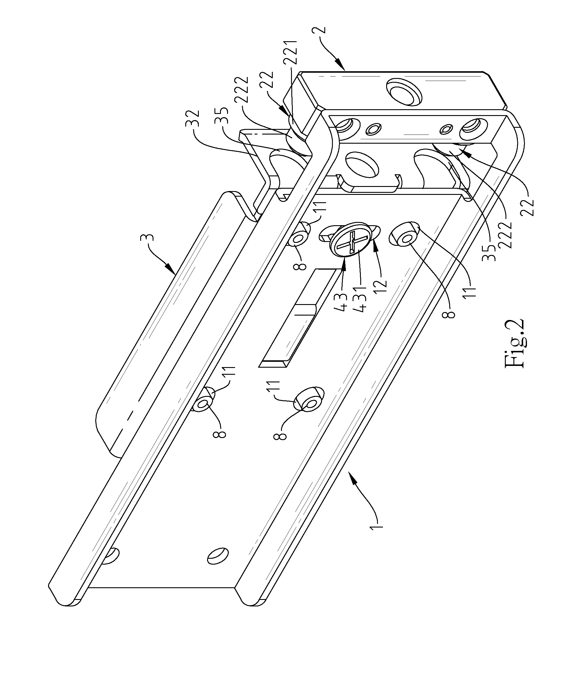
[0019]Referring to FIGS. 1-4, a quick release bracket assembly in accordance with the present invention is shown. The quick release bracket assembly comprises a bracket 1, a locating device 2, a positioning plate 3 and a locking device 4.

[0020]The bracket 1 comprises a plurality of locating holes 11 and a position-limit slot 12. The position-limit slot 12 defines a plurality of position-limit protrusions 121 and a plurality of position-limit grooves 122 alternatively arranged along one side edge thereof.

[0021]The locating device 2 comprises a base frame 21, and a plurality of locating rods 22 located at a top surface of the base frame 21. The base frame 21 is fixedly mounted at one side of the bracket 1 in such a manner that the locating rods 22 extend in direction toward the position-limit slot 12 of the bracket 1. Further, the locating rods 22 are stepped rod members, each ach comprising a first locating rod portion 221 outwardly extended from the base frame 21 and having a relati...


PUM


Abstract

A quick release bracket assembly includes a bracket, a locating device affixed to one end of the bracket, a positioning plate slidably coupled to the bracket and movable toward or away from the locating device, and a locking device movably mounted at the positioning plate and providing a spring member for pulling the positioning plate in direction toward said locating device. In installation in a rack, pull the positioning plate away from the locating device, and then attach the locating device to the rack, and then release the hand from the positioning plate for enabling the positioning plate to be pulled back by the spring member into engagement with the locating device.

Description

BACKGROUND OF THE INVENTION[0001]1. Field of the Invention[0002]The present invention relates to quick release bracket technology and more particularly, to a quick release bracket assembly, which allows movement of a positioning plate on the surface of a bracket relative to a locating device between a locking position and an unlocking position, facilitating quick mounting and dismounting.[0003]2. Description of the Related Art[0004]When mounting a sliding rail in a housing of a computer server, the sliding rail is connected to a bracket, and then the bracket is fastened to the inside of the housing of the computer server. After installation, sliding rails and brackets are disposed at different elevations inside the housing of the computer housing. When detaching one sliding rail and the associating bracket from the housing of the computer server, the sliding rail and the associating bracket cannot be detached in the vertical direction. According to the conventional technique, the di...

Claims


Application Information

Patent Timeline
Patent Type & Authority Patents(United States)
IPC IPC(8): F16M13/00F16M13/02H05K7/14F16B2/12
CPCH05K7/1489F16M13/022F16B2/12
Inventor CHANG, FU-TIEN
Owner NAN JUEN INT CO LTD
Learn More