
Convertible iron

a technology of irons and ironing plates, applied in the field of irons and ironing solutions, can solve the problems of inability to quickly touch-up garments, long setup and teardown times of devices, and additional storage space and setup time of irons

Inactive Publication Date: 2016-12-27
DIERKER BRANDON
View PDF56 Cites 6 Cited by
  • Summary
  • Abstract
  • Description
  • Claims
  • Application Information

AI Technical Summary

Benefits of technology

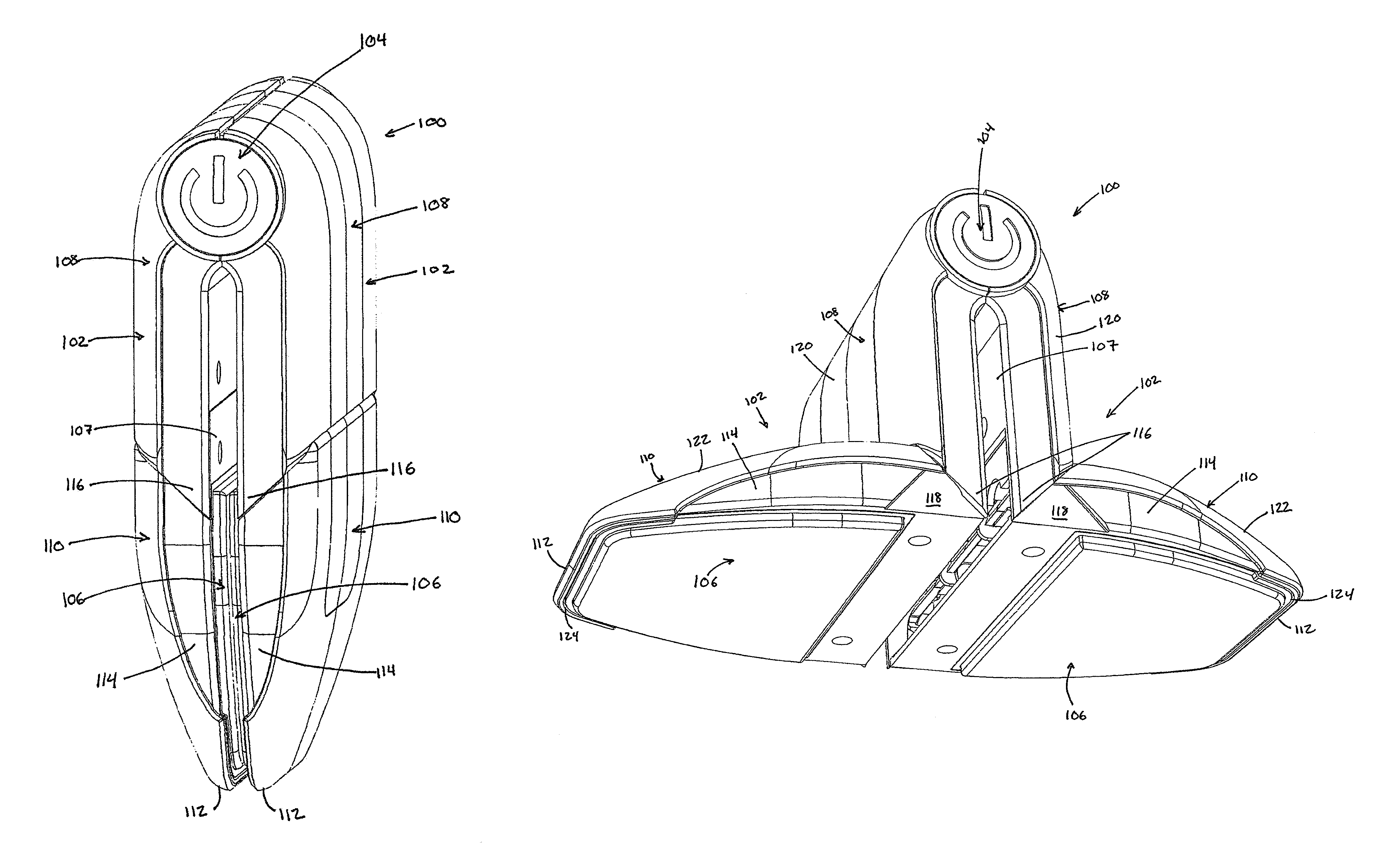
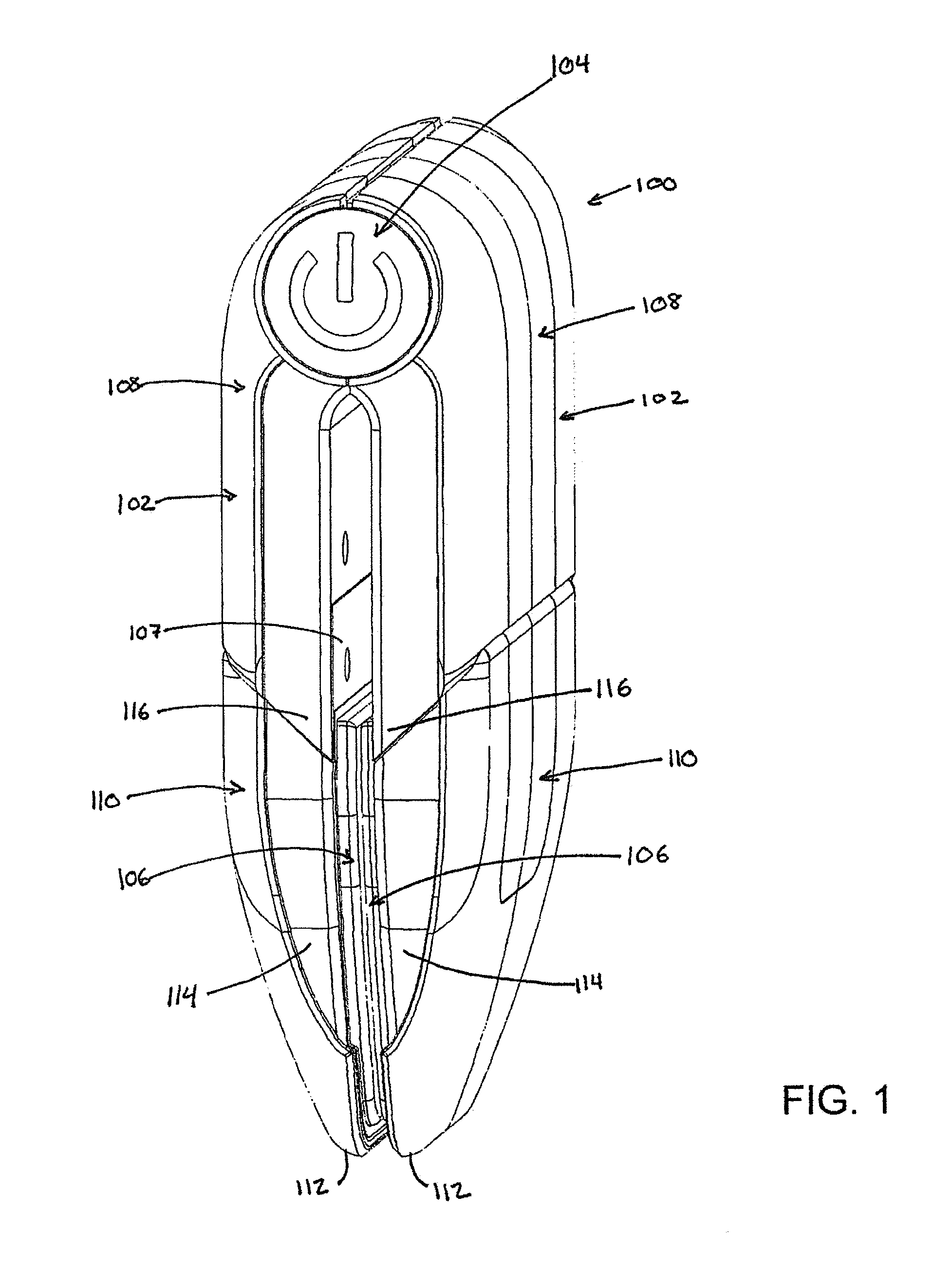
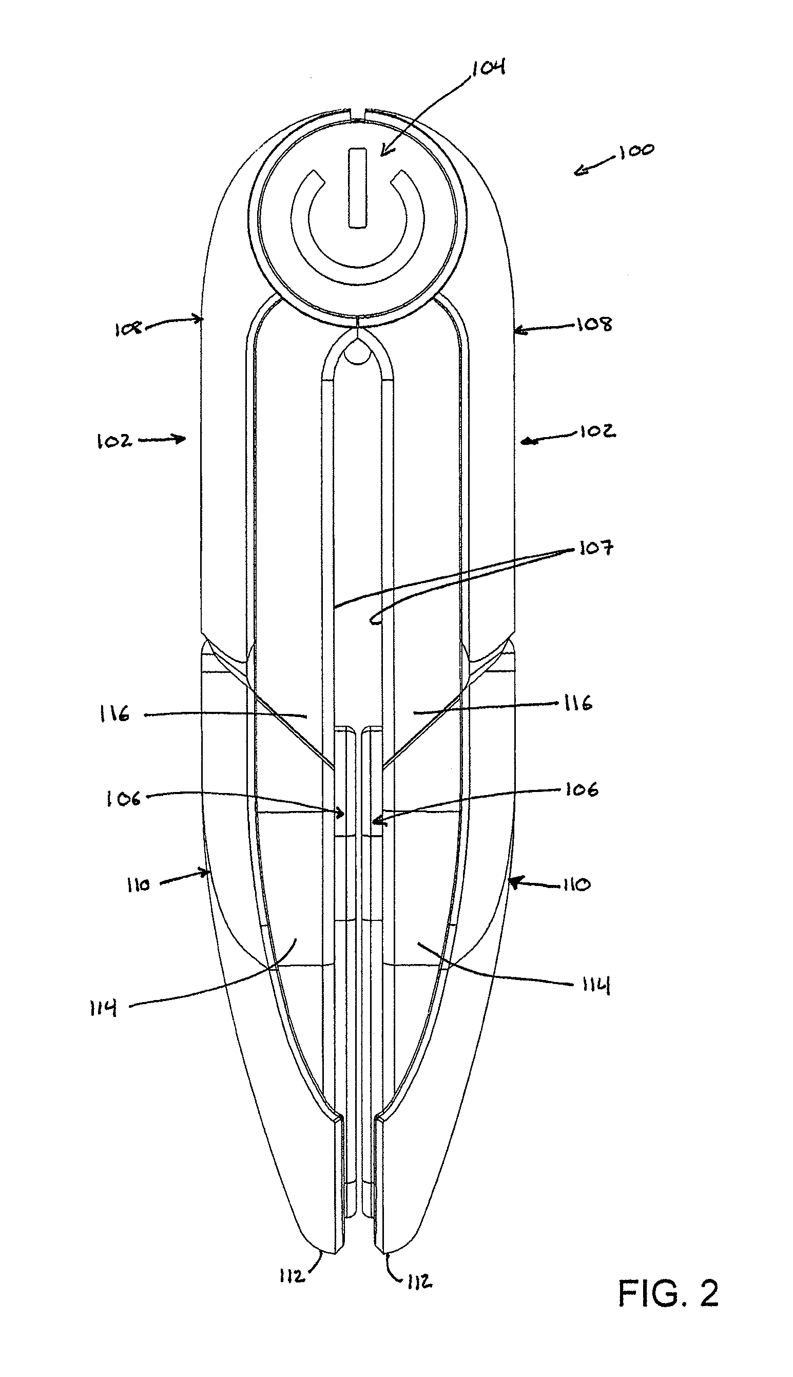
The present invention provides an apparatus and method for converting a convertible iron. The convertible iron has adjustable wings that can be moved between a detailing position and an ironing position. The adjustable wings are connected to a pivoting hub, and a heating plate is connected to the first adjustable wing. The heating plate can be actuated by a user and has multiple temperature settings. The convertible iron also includes a chamfer and a heat shield to guide uneven surfaces towards the heating plate and protect the article from excessive heat. The method of converting the convertible iron involves rotating the adjustable wings between the detailing position and the ironing position. The technical effects of the invention include improved flexibility and versatility in the use of a convertible iron, as well as improved safety and efficiency in the ironing process.

Problems solved by technology

These devices often require long setup and teardown times to allow the heating element to reach operating temperature and then to cool back down after use.
Traditional irons also have a heating element that is unshielded and uncovered, which requires constant monitoring during the cooling process.
Traditional irons may require an ironing board or other large, flat surface on which to iron the garments, which require additional storage space and setup time.
While useful for large ironing projects, these types of irons are incapable of quickly touching-up a garment without the wearer first removing the garment and setting up the iron and ironing board.
Applicant has identified a number of deficiencies and problems associated with conventional ironing technologies.

Method used


Image

  • Convertible iron
  • Convertible iron
  • Convertible iron

Examples


Embodiment Construction

[0034]The present invention will be described more fully hereinafter with reference to the accompanying drawings, in which some, but not all embodiments of the inventions are shown. Indeed, these inventions may be embodied in many different forms and should not be construed as limited to the embodiments set forth herein; rather, these embodiments are provided so that this disclosure will satisfy applicable legal requirements. Like numbers refer to like elements throughout. The terms top, bottom, side, up, down, upwards, downwards, vertical, horizontal, and the like as used below do not imply a required limitation in all embodiments of the present invention but rather are used herein to help describe relative direction or orientation in the example embodiments illustrated in the figures. The drawings may omit illustration of certain heating materials, padding, insulation, and other coverings to facilitate ease of visibility and understanding of features of the invention. As used in t...


PUM

PropertyMeasurementUnit
temperaturesaaaaaaaaaa

Abstract

Provided herein are a convertible iron and methods of manufacturing and converting the same. The iron may include a first adjustable wing and a second adjustable wing joined to a pivoting hub, such that the adjustable wings are configured to pivot about the hub with respect to each other. The iron may include a heating plate connected to at least the first adjustable wing. At least a portion of each adjustable wing may be configured to rotate between a detailing position and an ironing position. In the detailing position, the portions of each adjustable wing may be substantially parallel, such that the adjustable wings are substantially opposing one another and may be configured to receive an article therebetween for ironing. In the ironing position, the portions of each adjustable wing may be substantially coplanar and may be configured to engage a same side of a surface of an article for ironing.

Description

CROSS-REFERENCE TO RELATED APPLICATIONS[0001]This application claims priority to U.S. Design Application No. 29 / 503,839, which is entitled “Adjustable Iron” and was filed Sep. 30, 2014, and also claims priority to U.S. Provisional Application No. 61 / 941,827, which is entitled “Adjustable Shirt Collar Iron” and was filed Feb. 19, 2014, which references are hereby incorporated by reference in their entireties.FIELD OF THE INVENTION[0002]The present invention generally relates to irons and ironing solutions for smoothing imperfections in garments and other articles.BACKGROUND OF THE INVENTION[0003]Irons are traditionally used to straighten or flatten a wrinkled or misshaped garment. Household irons are large, heavy devices that use a heating surface to smooth imperfections in garments. These devices often require long setup and teardown times to allow the heating element to reach operating temperature and then to cool back down after use. Traditional irons also have a heating element t...

Claims


Application Information

Patent Timeline
Patent Type & Authority Patents(United States)
IPC IPC(8): D06F75/24D06F75/30D06F75/38
CPCD06F75/30D06F75/24D06F75/38Y10T29/49002
Inventor DIERKER, BRANDON
Owner DIERKER BRANDON
Learn More