Vehicle power transmission device

a technology of transmission device and transmission device, which is applied in the direction of mechanical equipment, transportation and packaging, and transportation of fuel, can solve the problems of reducing affecting the efficiency of the internal combustion engine, and increasing the size of the device, so as to reduce the loss of power, prevent or suppress the shift shock, and increase the speed ratio range

Active Publication Date: 2016-12-20
AISIN CORP
View PDF14 Cites 3 Cited by
  • Summary
  • Abstract
  • Description
  • Claims
  • Application Information

AI Technical Summary

Benefits of technology

[0013]The invention is made by focusing on the above-described technical inconvenience, and it is an object of the invention to provide a vehicle power transmission device that includes a continuously variable transmission, that is able to set a speed ratio exceeding a maximum speed ratio or minimum speed ratio that can be set by the continuously variable transmission and that is easy to reduce in size and excellent in durability.
[0030]When the brake mechanism is engaged instead of the first clutch mechanism, rotation of the reaction element is stopped, and the output element rotates in a direction opposite to the direction in which the input element rotates, so the vehicle is able to travel backward. In this case, torque is transmitted from the output element to the output shaft via the gear train and the third clutch mechanism, so the speed ratio is allowed to be set to a large speed ratio that cannot be set by the continuously variable transmission. In terms of this point as well, it is possible to increase the speed ratio range of the whole of the power transmission device.
[0031]In addition, torque is input from the output shaft side when the vehicle; decelerates. By providing the second clutch mechanism between the driven-side member of the continuously variable transmission and the output shaft and releasing the second clutch mechanism, it is possible to avoid co-rotation of the continuously variable transmission by interrupting torque that is input from the output shaft to the continuously variable transmission.
[0032]When the first clutch mechanism is released in a state where the continuously variable transmission is controlled so that the speed ratio becomes close to the speed ratio of the gear train and the second clutch mechanism is engaged, the input shaft and the output shaft are coupled to each other via the continuously variable transmission and the second clutch mechanism, and the gear train is disconnected from the input shaft. Thus, it is possible to set the speed ratio as needed by the continuously variable transmission. In this case, when the first clutch mechanism and the second clutch mechanism each are formed of a friction clutch, by gradually changing the amount of torque assigned to the first clutch mechanism and the second clutch mechanism, it is possible to smooth a change in the torque of the output shaft With this configuration, it is possible to prevent or suppress a shift shock or a feeling of strangeness due to a change in driving force.
[0033]When the third clutch mechanism is released in this state, the gear train is also interrupted from the output shaft. Therefore, it is possible to eliminate a situation that the gear train is co-rotated in the case where the vehicle travels while transmitting torque by the continuously variable transmission, a situation that torque is input from not only the input element of the forward-reverse switching mechanism but also the output element and then a rotation speed difference between the elements increases, or the like. As a result, it is possible to not only reduce a loss of power but also improve durability and suppress noise and vibrations. By forming the third clutch mechanism from an intermeshing clutch, it is possible to simplify the configuration of the overall power transmission device and reduce the size of the overall power transmission device. In addition, engagement or release is carried out in a state where almost no torque is applied, so engagement and release operations are not impaired.
[0034]According to the invention, the first to third clutch mechanisms and the brake mechanism each may be formed of a single mechanism, such as a friction or intermeshing clutch, brake, or the like, so it is possible to simplify the configuration of the overall power transmission device and reduce the size of the overall power transmission device. Particularly, by forming the forward-reverse switching mechanism from the single-pinion-type or double-pinion-type planetary gear train, the axial length of the overall power transmission device is reduced, with the result that it is possible to improve vehicle mountability.

Problems solved by technology

In addition, an operating point at which the efficiency of the internal combustion engine is high is limited.
If a hydraulic device that generates a large hydraulic pressure, is provided in preparation for a start-moving time that is a relatively short time as a driving state of the vehicle, a driving device and a hydraulic system for the driving device increase in size, and there is a possibility that fuel economy deteriorates as the hydraulic device generates a high hydraulic pressure.
However, the torque transmission direction of the one-way clutch is limited to one direction, while torque needs to be transmitted in any one of forward and reverse directions at the time when the vehicle actually travels, and it is required not to cause the one-way clutch to function depending on the configuration of the torque transmission path.
Thus, with the configuration described in each of the above-described publications, even when it is possible to avoid or suppress application of large torque to the continuously variable transmission at the start of the vehicle, the configuration of the device as a whole increases in size, so there is a possibility that vehicle mountability is impaired.
Therefore, there occurs a large rotation speed difference between the sun gear, pinion gears and the ring gear, and there is a possibility that this causes a loss of power, degradation of lubricating oil, noise or vibrations.
As a result, as in the case of the device described in JP 2005-308041 A, there occurs a large rotation speed difference between the sun gear, the pinion gears and the ring gear, and there is a possibility that this causes a loss of power, degradation of lubricating oil, noise or vibrations.

Method used


Image

  • Vehicle power transmission device
  • Vehicle power transmission device
  • Vehicle power transmission device

Examples


Embodiment Construction

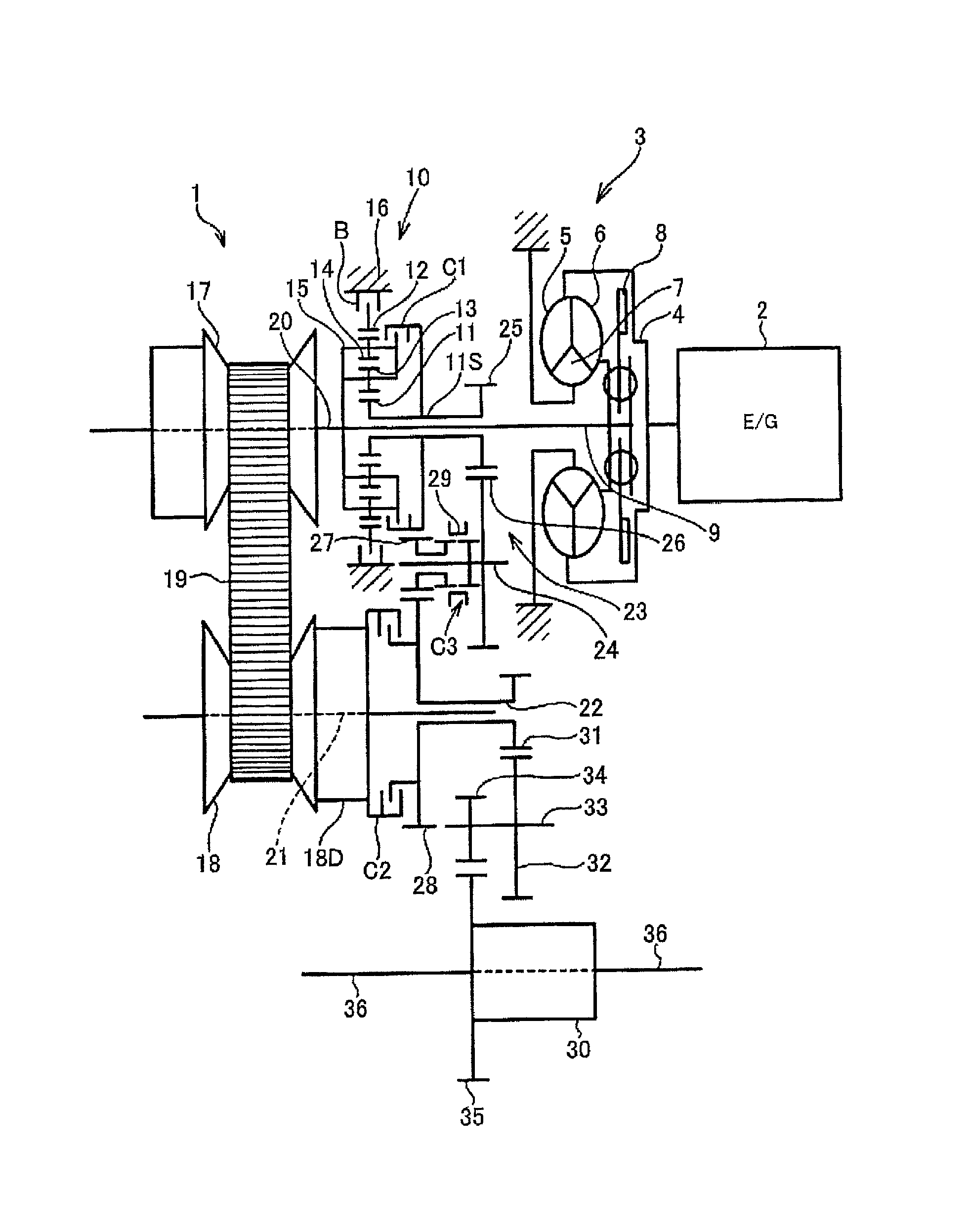
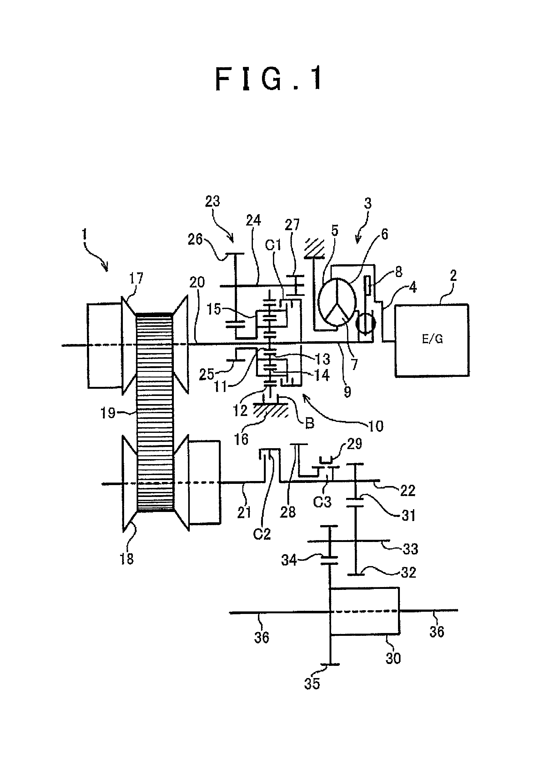
[0046]A power transmission device according to the invention is a device for transmitting power output from a driving force source, such as an engine and a motor, to a drive wheel and is a device having a shift function. That is, the power transmission device is a device generally called a transmission or a transaxle. Particularly, a device intended by the invention is a power transmission device including a continuously variable transmission and a gear train. The continuously variable transmission and the gear train are arranged in parallel with each other between an input shaft and an output shaft. The gear train has a predetermined speed ratio (gear ratio). The continuously variable transmission may be an existing known belt-type continuously variable transmission or toroidal-type continuously variable transmission. The belt-type continuously variable transmission is suitable for a power transmission device that is mounted on a front-engine front-drive vehicle (FF vehicle). The t...


PUM


Abstract

There is a vehicle power transmission device in which a continuously variable transmission and a gear train are provided between an input shaft and an output shaft so as to be able to transmit torque between the input shaft and the output shaft, the gear train has at least one speed ratio that cannot be set by the continuously variable transmission. In the vehicle power transmission device, a forward-reverse switching mechanism is arranged along the same axis as an axis of the input shaft, a first clutch mechanism and a brake mechanism are provided, a second clutch mechanism is provided in a first torque transmission path that is routed from the input shaft to the output shaft via the continuously variable transmission, a third clutch mechanism is provided in a second torque transmission path that is routed from the output element to the output shaft via the gear train.

Description

TECHNICAL FIELD[0001]The invention relates to a device for transmitting power output from a driving force source of a vehicle and, more particularly, to a power transmission device that includes a transmission path including a continuously variable transmission and another transmission path provided in parallel with the former transmission path.BACKGROUND ART[0002]An internal combustion engine that is generally used as a driving force source of a vehicle has such a characteristic that an output torque increases with an increase in rotation speed, whereas a driving force that is required of a vehicle is generally large at a low vehicle speed and is relatively small at a high vehicle speed. That is, a vehicle requires a torque having an inverse characteristic to a torque based on the output characteristic of the internal combustion engine. In addition, an operating point at which the efficiency of the internal combustion engine is high is limited. Therefore, in a vehicle that uses the...

Claims


Application Information

Patent Timeline
Patent Type & Authority Patents(United States)
IPC IPC(8): F16H37/02
CPCF16H37/022F16H2037/026F16H2200/0008F16H2200/2005F16H2200/2035
Inventor NAKAGAWA, HIDEKIYOSHIDA, MICHIONAKADA, HIROFUMIHABUCHI, RYOJI
Owner AISIN CORP
Why Eureka
Try Eureka