Multiple flexible seafloor-surface linking apparatus comprising at least two levels

Active Publication Date: 2016-12-13
SAIPEM SA
View PDF22 Cites 3 Cited by
  • Summary
  • Abstract
  • Description
  • Claims
  • Application Information

AI Technical Summary

Benefits of technology

The patent describes a way to reduce the space needed for flexible lines that connect to the sea floor, allowing more connections to be installed without interfering with each other. This is useful for offshore oil companies, who need to connect these lines to their platforms or FPSOs. The patent also includes a device to protect the flexible pipes from damage when they are being laid on a ship. These improvements make it easier to install and protect the flexible lines needed for offshore oil production.

Problems solved by technology

During a stage of designing the development of an oil field, the oil deposit is known incompletely, so production at full rate often makes it necessary, after a few years, to revise initial production plans and the organization of the associated equipment.

Method used


Image

  • Multiple flexible seafloor-surface linking apparatus comprising at least two levels
  • Multiple flexible seafloor-surface linking apparatus comprising at least two levels
  • Multiple flexible seafloor-surface linking apparatus comprising at least two levels

Examples


Embodiment Construction

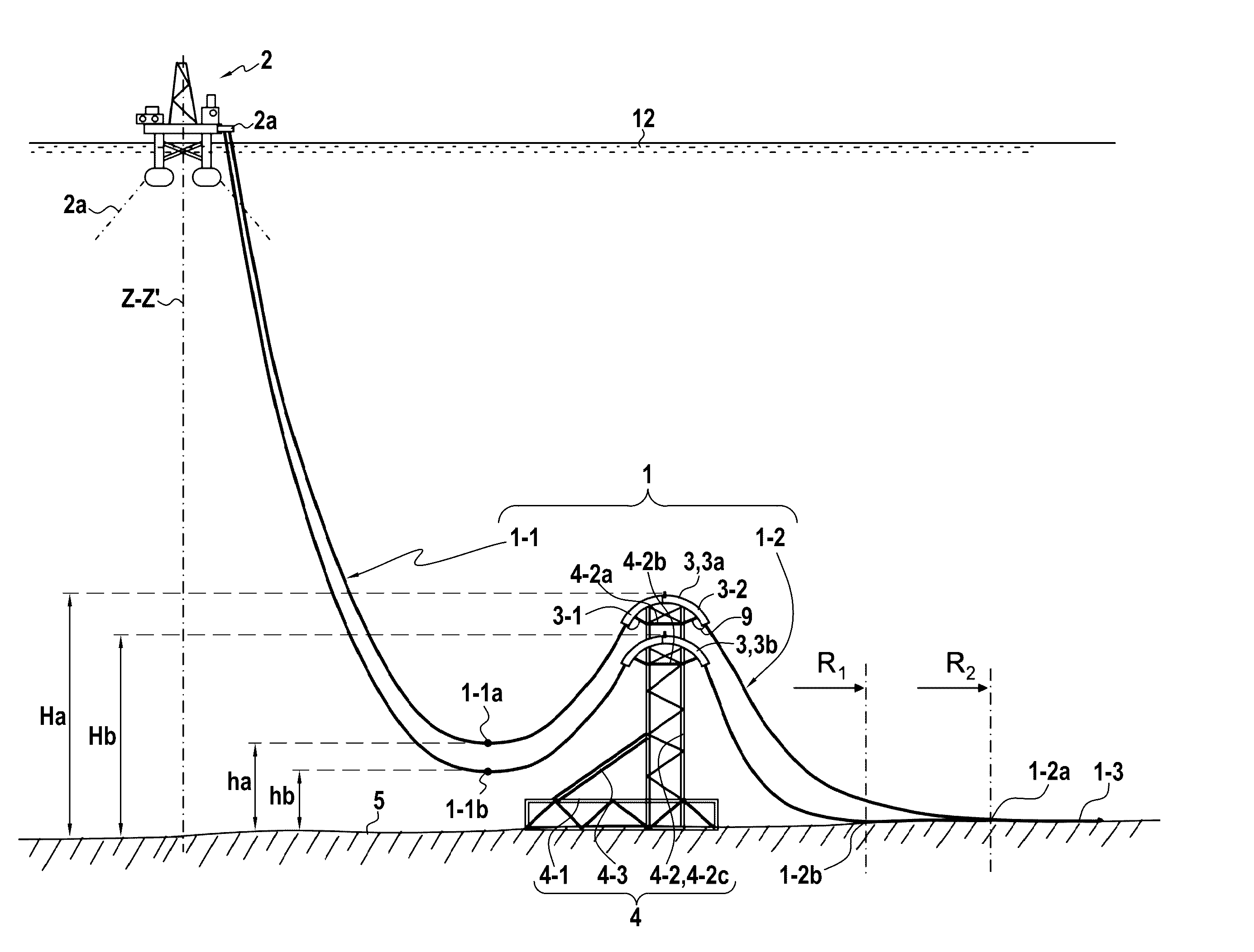
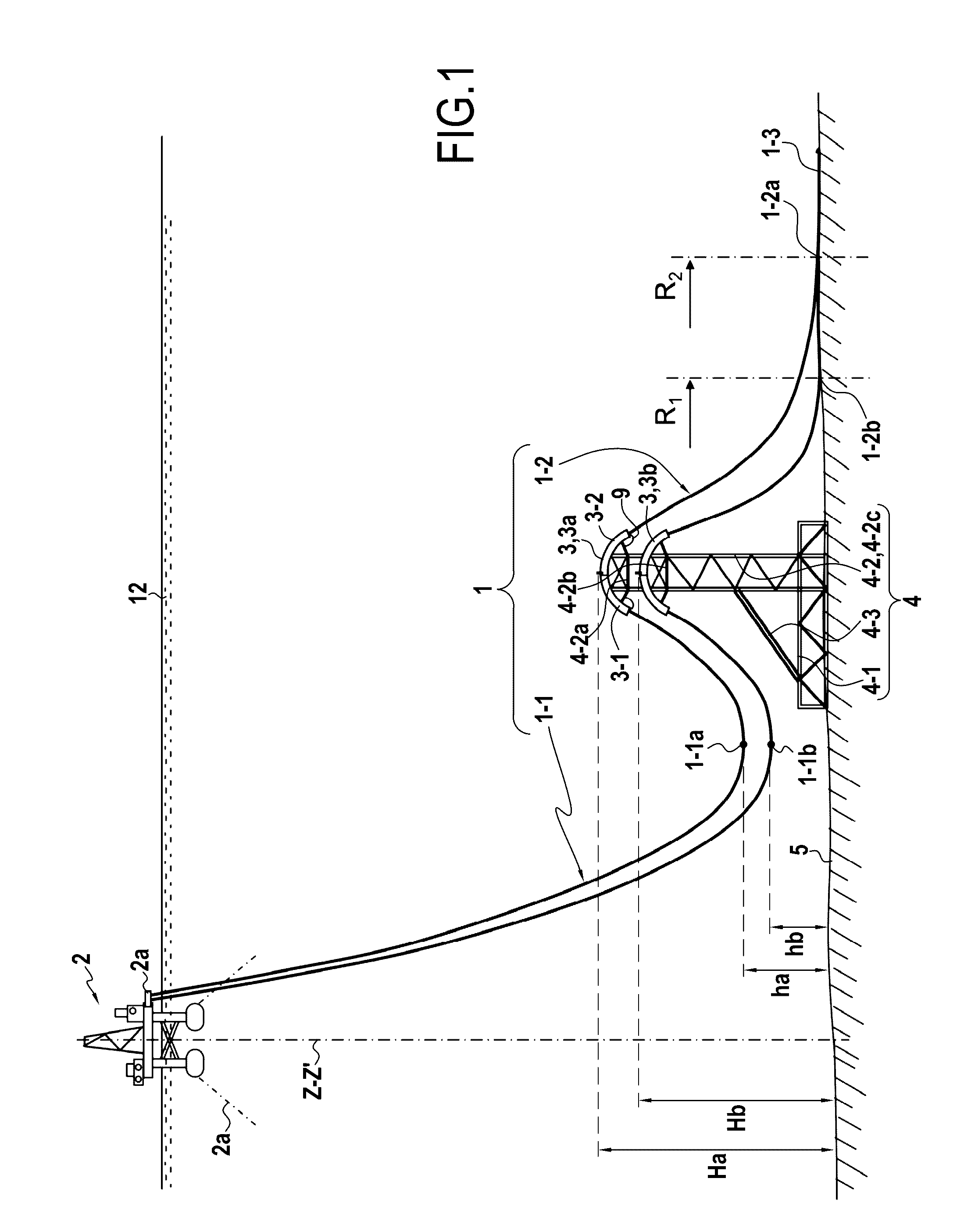
[0097]FIG. 1 shows a bottom-to-surface connection installation having two flexible pipes 1 connected at one end 2a to a semi-submersible floating platform 2 that is held in position by anchor lines 2a, with the other ends of said flexible pipes resting on the sea bottom 5 at 1-3. The two flexible pipes 1 extend at different heights and they come into contact with the sea floor 5 at contact points 1-2a and 1-2b that are at different distances from the axis ZZ′ of the floating support 2.

[0098]The bottom-to-surface connection installation has a rigid support structure 4 comprising a rigid vertical tower 4-2c constituted by a metal lattice structure supporting top and bottom rigid support elements 4-2a and 4-2b at its top, which two elements form horizontal beams, extending symmetrically on either side of the tower 4-2c. Top troughs 3a are fastened over the top beam 4-2a and bottom troughs 3b are fastened over the bottom beam 4-2b. All of the top and bottom troughs 3a and 3b are prefera...


PUM


Abstract

A bottom-to-surface connection installation between a common floating support and the sea bottom, having a plurality of flexible lines such as flexible pipes extending between said floating support and the sea bottom. The flexible lines are supported by respective ones of a plurality of troughs each trough lying between two pipe portions defining a first flexible line portion in a hanging double catenary configuration between the floating support and the trough, and a second flexible line portion in a single catenary configuration between the trough and the point of contact of the flexible pipe with the sea bottom. The installation has at least one support structure having a base-forming bottom portion resting on and / or anchored to, or embedded in the sea bottom and a top portion supporting at least two troughs, respectively a bottom trough and a top trough, the troughs being arranged at different heights in such a manner that the low point of the first flexible line portion passing via the bottom trough is situated below the low point of the first flexible line portion passing via the top trough.

Description

PRIORITY CLAIM[0001]This is a U.S. national stage of application No. PCT / FR2012 / 052717, filed on Nov. 23, 2012. Priority is claimed on France Application No. FR1160934, filed Nov. 30, 2011, the content of which is incorporated herein by reference.BACKGROUND OF THE INVENTION[0002]The present invention relates to an installation of multiple flexible bottom-to-surface connections between well heads, pieces of equipment, or the ends of undersea pipes resting on the sea bottom, and a floating support on the surface, the installation comprising a multiplicity of flexible lines, in particular flexible pipes, having their bottom ends connected to the ends of a plurality of undersea pipes resting on the sea bottom or directly to well heads or to pieces of equipment resting on the sea bottom.[0003]In the present description, the term “flexible line” is used to mean pipes or cables capable of accepting large amounts of deformation without that giving rise to significant return forces, such as ...

Claims


Application Information

Patent Timeline
IPC IPC(8): E21B17/01F16L3/01
CPCE21B17/015F16L3/01
Inventor PIONETTI, FRANCOIS REGIS
Owner SAIPEM SA
Why Eureka
Try Eureka